Method for assembling, repairing and setting test parameters of vertical probe card device

An assembly method and probe card technology, which are applied in the field of probe cards, can solve problems such as poor contact, damage to test devices, and affect pad contact, and achieve the effects of clear needle marks, good contact, and improved service life.

Active Publication Date: 2022-02-25
FTDEVICE TECH (SUZHOU) CO LTD
View PDF5 Cites 0 Cited by
  • Summary
  • Abstract
  • Description
  • Claims
  • Application Information

AI Technical Summary

Problems solved by technology

[0012] Flatness is the vertical distance between the highest and lowest points of the probe pin on the probe card, which defines the first time the probe tip The vertical displacement from the electrical contact to the last electrical contact. During the assembly process of the probe, the flatness problem exists, but the maximum flatness is required not to exceed 25mm. The flatness is rarely concerned, but it directly affects the contact with the probe. The contact of the solder pad directly or indirectly affects key test variables such as contact pressure, contact resistance and clarity of needle marks, how to overcome the problem of poor contact caused by flatness
[0013]Third, the repair and assembly of the probe
[0014] As an important consumable in wafer testing, changes in the physical shape of the probe tip will directly affect the test results, and may damage the test device, a large number of probes The needle tip of the medium probe is physically deformed or a large amount of extrusion causes the probe to bend sideways, and the next detection cannot be performed, but only a few cannot continue to detect, and most of the probes can still continue to work. The replaced probe card is due to repair , The assembly and replacement procedures are cumbersome and can only be scrapped, resulting in waste of resources

Method used


Image

  • Method for assembling, repairing and setting test parameters of vertical probe card device
  • Method for assembling, repairing and setting test parameters of vertical probe card device
  • Method for assembling, repairing and setting test parameters of vertical probe card device

Examples


specific Embodiment approach 1

[0083] This embodiment is an embodiment of a vertical probe card device.

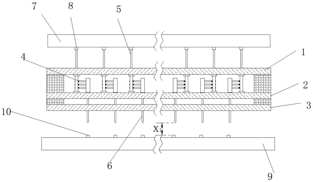
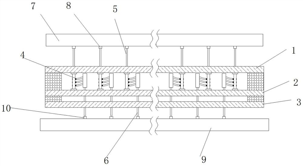
[0084] Such as Figure 1-10 As shown, a vertical probe card device disclosed in this embodiment includes an upper guide plate 1, a middle guide plate 2, a lower guide plate 3, a deformation connection device 4, a first probe 5, a second probe 6, a circuit board 7, The first welding pad 8; the upper guide plate 1, the middle guide plate 2 and the lower guide plate 3 are respectively provided with a plurality of vertical limit through holes, and a plurality of deformation connection devices are arranged in an array between the upper guide plate 1 and the middle guide plate 2 4. One end of the plurality of first probes 5 passes through the vertical limiting through hole of the upper guide plate 1 and is electrically connected to one end of the corresponding deformation connection device 4, and the other end is connected to the corresponding first solder joint on the circuit board 7. Pads 8 are connected, ...

specific Embodiment approach 2

[0118] This embodiment is an embodiment of a vertical probe card device.

[0119] A test parameter setting method for a vertical probe card device disclosed in this embodiment includes the following steps:

[0120] Step a, assumed length,

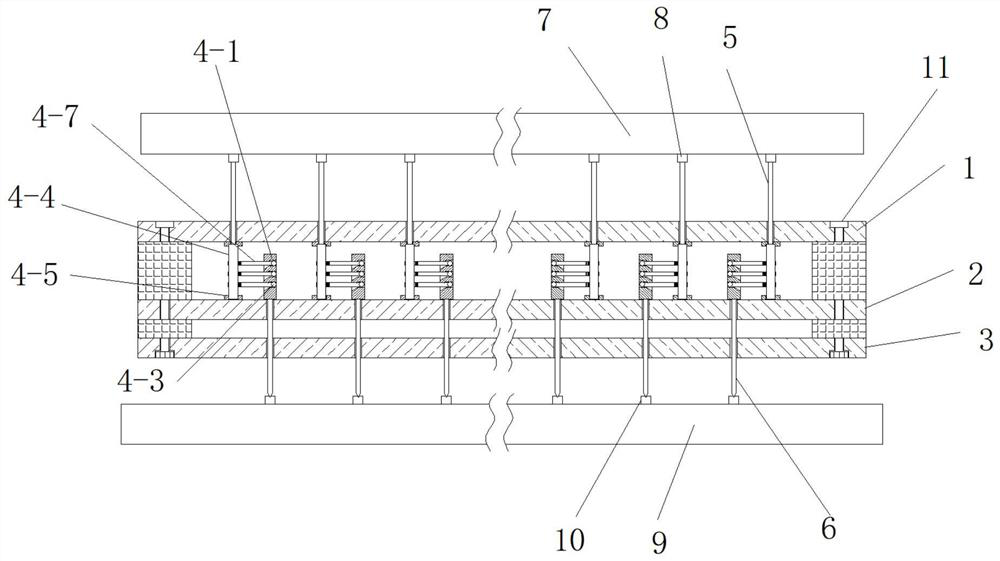
[0121] First assemble some vertical probe card devices to be tested. During the assembly process, the length of the elastic pins 4-7 arrayed on the side wall of the stabilizer 4-4 will be adjusted through the screw thread, and the effective length of the elastic pins 4-7 will be adjusted. , and the effective length of the elastic pins 4-7 is preliminarily set as S, and then the vertical probe card device is assembled;

[0122] Step b. Plane test

[0123] The assembled vertical probe card to be tested is installed on the bearing platform of the test probe station, and the contact flatness test is carried out one by one, and the difference between the highest point and the lowest point of the second probe 6 tip on the vertical probe card is...

specific Embodiment approach 3

[0142] This embodiment is an embodiment of a vertical probe card device.

[0143] A method for calculating the displacement of a probe of a vertical probe card device, comprising the following steps:

[0144] Step a, measure elastic modulus E and moment of inertia I of elastic needle 4-7;

[0145] Step b. Force analysis calculates the concentrated load acting on one end of the elastic needle 4-7 by the limiting member 4-1 through the limiting bead 4-3. When the number of elastic needles is n, calculate the concentrated load acting on the elastic needle 4. The concentrated load of the spacer beads 4-3 at one end of -7 is

[0146] Step c. Draw concentrated load The bending moment diagram when acting on the limit bead 4-3 and on the elastic pin 4-7, that is, M P picture;

[0147] Step d. Draw the unit load The bending moment diagram when acting on the limit bead 4-3 and on the elastic pin 4-7, that is, M 1 picture;

[0148] Step e, calculate the longitudinal displaceme...


PUM


Abstract

The invention discloses a method for assembling, repairing and setting test parameters of a vertical probe card device, and relates to the technical field of probe cards. The assembling method sequentially executes the steps of needle connecting, distance adjusting, piece hanging, plate penetrating, fixing and electric connecting. The repairing method comprises the steps of overall dismounting, fixed mounting, dismounting and separating, probe replacing, probe repairing and reassembling in sequence. The test parameter setting method sequentially executes the steps of length assuming, plane testing, contact pressure calculation, deformation calculation, height setting and effective length calculation. According to the method for assembling, repairing and setting the test parameters of the vertical probe card device, the problems of assembling, repairing and test parameter setting of a vertical probe card with an upper guide plate, a middle guide plate, a lower guide plate, a deformation connecting device, a first probe, a second probe, a circuit board and a first welding pad are solved in sequence.

Description

technical field [0001] The invention relates to a method for assembling, repairing and testing parameter setting of a vertical probe card device, which relates to the technical field of probe cards. Background technique [0002] The generation of a chip mainly needs to go through four major links: design, manufacturing, packaging, and testing. After the wafer manufacturing is completed, it is necessary to test the freshly released wafer. In this link, the electrical performance of each chip will be tested. , wafer inspection has two main purposes: [0003] First, identify qualified chips to enter the packaging process, saving unnecessary packaging costs; [0004] Second, evaluate the electrical parameters of the circuit to maintain the quality level of the process. [0005] A very important consumable in wafer testing - probe card, probe card is mainly used in wafer testing, it is the medium between wafer and electronic testing system in wafer testing, engineering verifica...

Claims


Application Information

Patent Timeline
Patent Type & Authority Applications(China)
IPC IPC(8): G01R31/28G01R1/067
CPCG01R31/28G01R1/067
Inventor 王强金永斌贺涛丁宁朱伟
Owner FTDEVICE TECH (SUZHOU) CO LTD
Why Eureka
Try Eureka