Horizontal pushing type narrowing machine

A narrow-band, flat push technology, applied in the direction of conveyors, conveyor objects, mechanical conveyors, etc., can solve the problem that the number of car sections cannot be increased or decreased at will, and achieve the effect of increasing or decreasing the length and reducing the design pressure

Pending Publication Date: 2022-02-25
江苏居尚机电科技有限公司
View PDF0 Cites 4 Cited by
  • Summary
  • Abstract
  • Description
  • Claims
  • Application Information

AI Technical Summary

Problems solved by technology

However, since the power of the motor has been determined after the selection is completed, the number of car sections cannot be increased or decreased at will. When transfer machines of different lengths are required, redesign is required.

Method used


Image

  • Horizontal pushing type narrowing machine
  • Horizontal pushing type narrowing machine
  • Horizontal pushing type narrowing machine

Examples


Embodiment 1

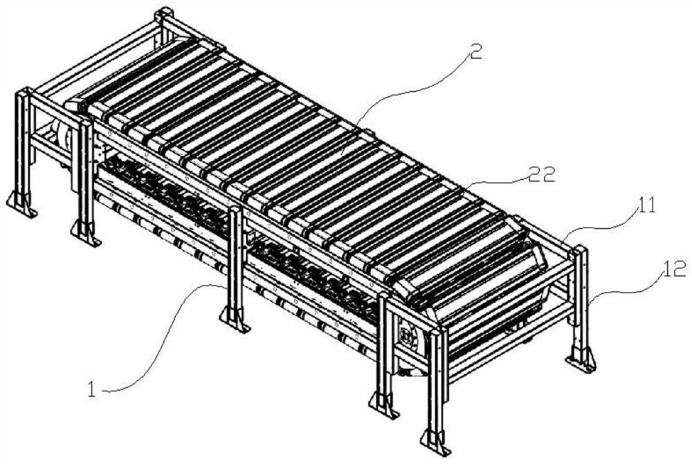
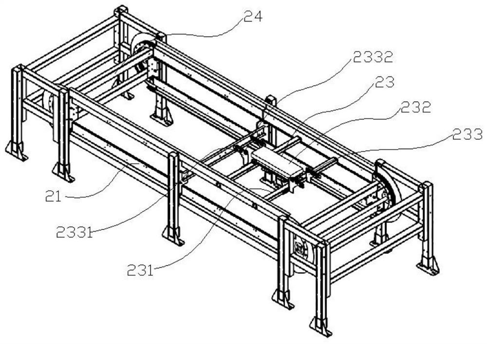
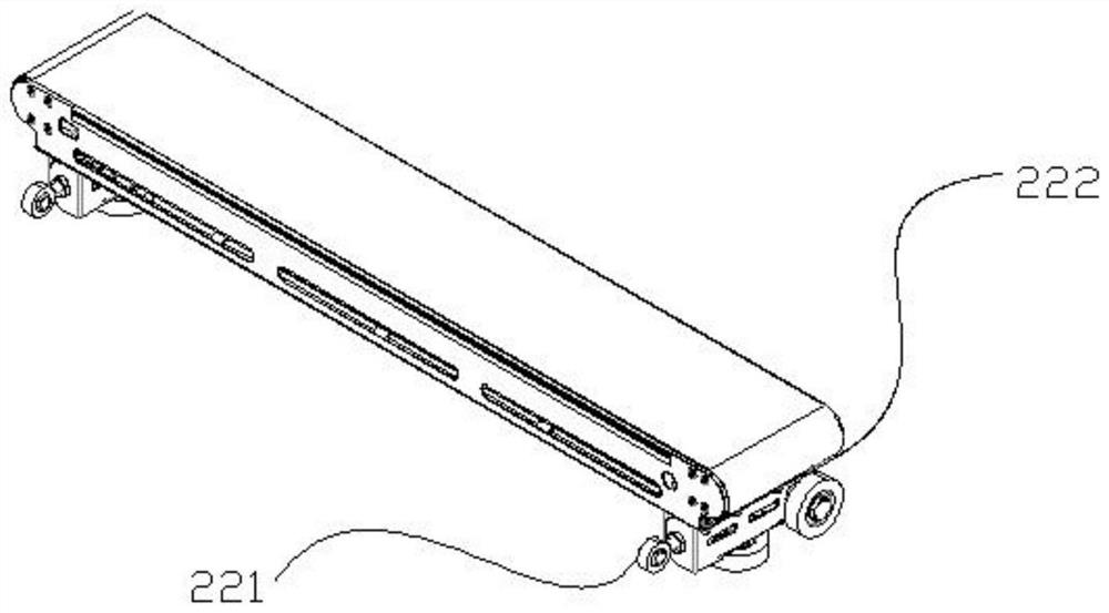
[0025] In order to solve the existing narrow-band machines in the prior art, once the production is completed, it is difficult to adjust the pitch and height, and occupy a large space. Figure 1-3 As shown, it includes a bracket 1 and a narrowband machine body 2 arranged on the bracket; the narrowband machine body 2 includes two circular tracks 21, two ends of which are arranged on the circular track 21 and can be connected to the circular track 21 Several trolleys that slide up, are used to drive the trolleys to slide on the circular track 21 and are arranged between the two circular rails 21. A flat push motor assembly 23, and several trolleys form a ring that matches the circular track 21. .

[0026] When the flat-push narrowband machine provided by Embodiment 1 of the present invention is working, the flat-push motor 232 will push the trolley 22 to slide on the circular track 21, so as to realize the movement of the trolley 22 on the circular track 21, thereby realizing th...


PUM


Abstract

The invention, which relates to the technical field of electromechanical equipment, discloses a horizontal pushing type narrowing machine comprising a support and a narrowing machine body arranged on the support. The narrowing machine body comprises two annular rails, a plurality of trolleys and a horizontal pushing type motor assembly, the two ends of each trolley are arranged on the annular rails, the trolleys can slide on the rails, the horizontal pushing type motor assembly is used for driving the trolleys to slide on the rails and is arranged between the two annular rails, and the trolleys form a ring matched with the annular rails. The length of the horizontal pushing type narrowing machine can be increased or decreased by adjusting the length of the annular rail, increasing or decreasing the number of the trolleys and selecting a proper number of flat-pushing type motor assemblies, so that the horizontal pushing type narrowing machine is suitable for more occasions, and the design pressure is relieved.

Description

technical field [0001] The invention relates to the technical field of electromechanical equipment, in particular to a flat-push narrowband machine. Background technique [0002] In industrial production, material transportation is often required. In the product assembly line and warehousing and logistics handling, the conveying line is often used in the transportation of items. For example, a plurality of conveying lines are arranged vertically and horizontally in a delivery yard, and transfer machines are arranged at intersections of the conveying lines. Then, through the running transfer machine, the conveying direction of the article is changed, and the article is sent into or moved out of the main conveying line from the crossing position. The transfer machine enables items to enter and exit the main and auxiliary conveying lines conveniently, without collision, extrusion or even damage to the external structure due to the stacking of items during the transmission pro...

Claims


Application Information

Patent Timeline
Patent Type & Authority Applications(China)
IPC IPC(8): B65G35/00B65G41/00B65G47/24B65G39/18
CPCB65G35/00B65G41/003B65G47/24B65G39/18
Inventor 赵怡李攀董官成向君华
Owner 江苏居尚机电科技有限公司
Why Eureka
Try Eureka