Compressed air energy storage system with dynamic load response function and control method

A compressed air energy storage and dynamic load technology, which is applied in steam applications, machines/engines, steam engine devices, etc., can solve the problems of low automation level and achieve the effect of improving support capacity

Pending Publication Date: 2022-02-25
中煤能源研究院有限责任公司
View PDF0 Cites 0 Cited by
  • Summary
  • Abstract
  • Description
  • Claims
  • Application Information

AI Technical Summary

Problems solved by technology

[0003] Aiming at the problem of low automation level in the manual control stage of the prior art, the present invention provides a compressed air energy storage system with a dynamic load response function and a control method. The compressed air energy storage system has a simple structure and realizes ener

Method used


Image

  • Compressed air energy storage system with dynamic load response function and control method
  • Compressed air energy storage system with dynamic load response function and control method
  • Compressed air energy storage system with dynamic load response function and control method

Examples


Example Embodiment

[0040] In order to better understand the present invention, the technical solutions in the embodiments of the present invention will be described in contemplation, and It is an embodiment of the invention, not all of the embodiments. Based on the embodiments in the present invention, those of ordinary skill in the art may belong to the scope of the present invention in the range of the present invention without all other embodiments obtained without making creative labor.

[0041] It should be noted that the specification and claims of the present invention and the terms "first", "second", "second", or the like are used to distinguish a similar object without having to describe a particular order or award order. It should be understood that the data such as use can be interchanged in appropriate, so that the embodiments of the invention described herein can be implemented in the order other than those illustrated or described herein. Moreover, the terms "including" and "have" and ...


PUM


Abstract

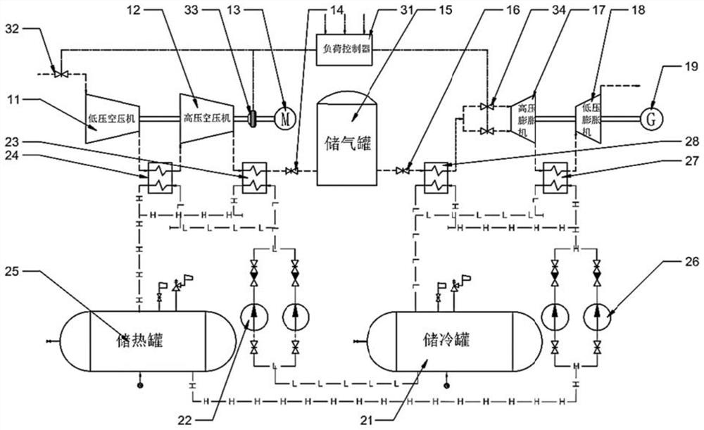
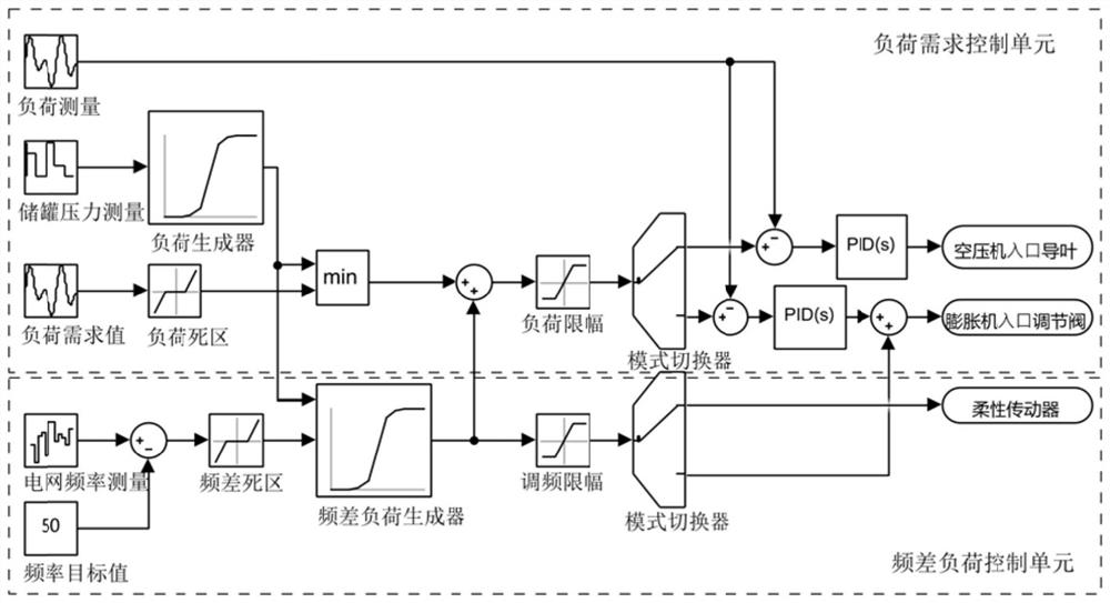
The invention provides a compressed air energy storage system with a dynamic load response function and a control method. Automatic load adjustment in a compressed air energy storage stage and an energy release stage is realized through a load controller, and the load controller comprises a load demand control unit and a frequency difference load control unit, wherein the input end of the load demand control unit is connected with a first signal receiving module, the output end of the load demand control unit is connected with a first signal processor and a first signal output module, and the input end of the frequency difference load control unit is connected with a second signal receiving module; the output end of the frequency difference load control unit is connected with a second signal processor and a second signal output module; through module control, response and primary frequency modulation of dynamic load requirements of compressed air energy storage in the two stages of energy storage and energy release are effectively achieved, and the supporting capacity of the compressed air energy storage on a power grid under the safe boundary condition is effectively improved.

Description

technical field [0001] The invention relates to the technical field of electric energy storage, in particular to a compressed air energy storage system with a dynamic load response function and a control method. Background technique [0002] Compressed air energy storage is one of the key supporting technologies for building a new power system with new energy as the main body and realizing large-scale energy storage. Compressed air energy storage mainly drives the air compressor by using the remaining electricity when the load of the power system is low. Pressing into a large-capacity air storage chamber, that is, converting electrical energy into storable potential energy of compressed air, when the power generation capacity of the system is insufficient, the expander is then driven to generate power to meet the peak-shaving needs of the system. Compressed air energy storage has the advantages of large capacity, long service life, and good economy. However, limited by the ...

Claims


Application Information

Patent Timeline
IPC IPC(8): F01K7/02F01K27/00F01K13/00F01K17/02F04B37/12F04B41/02
CPCF01K7/02F01K27/00F01K13/00F01K17/02F04B37/12F04B41/02Y02E60/16
Inventor 王龙飞郑忠友李庆王帅董宝光武进李超
Owner 中煤能源研究院有限责任公司
Why Eureka
Try Eureka