
Exhaust throttle valve

An exhaust throttle valve and valve body technology, which is applied in engine control, machine/engine, mechanical equipment, etc., can solve the problems of low life and high failure rate of exhaust throttle valve, and achieve cost reduction, simple structure, and improved performance. effect of benefit

Pending Publication Date: 2022-02-25
安徽奥众汽车部件有限公司
View PDF0 Cites 0 Cited by
  • Summary
  • Abstract
  • Description
  • Claims
  • Application Information

AI Technical Summary

Problems solved by technology

Due to the relatively high temperature of the gas discharged from the automobile engine, the high-temperature exhaust gas passes through the exhaust throttle valve, and the exhaust throttle valve is in a harsh gas environment. In the prior art, due to the high temperature of the exhaust gas, the failure rate of the exhaust throttle valve is caused. high, low life

Method used


Image

  • Exhaust throttle valve
  • Exhaust throttle valve
  • Exhaust throttle valve

Examples


Embodiment

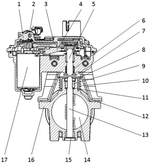
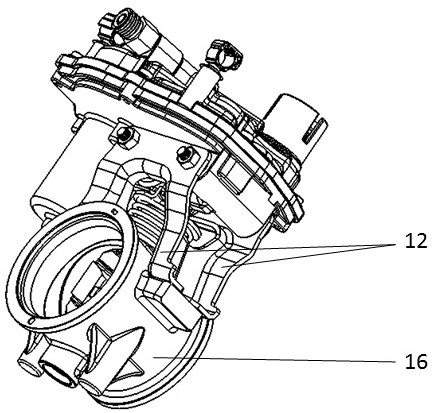
[0025] see Figure 1 to Figure 6 , a preferred embodiment of the exhaust throttle valve of the present invention is composed of a valve body 16, a driven mechanism, a transmission mechanism, a speed change mechanism and a power mechanism. When the power mechanism outputs power, the power mechanism drives the second transmission device through the transmission mechanism, and drives the first transmission device to make the driven mechanism act. When the power mechanism does not output, the first transmission device drives the driven mechanism to return to the initial position.

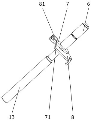
[0026] The driven mechanism is located in the valve body 16 and includes the throttle plate 14 and the valve shaft 13 . The valve shaft 13 passes through the valve body 16, and the throttle plate 14 is rigidly fixed on the valve shaft 13, driven to rotate by the valve shaft 13, and regulates the gas flow rate of the exhaust throttle valve. A needle roller bearing 6 is arranged at the end of the valve ...


PUM


Abstract

The invention relates to the technical field of automobile engine exhaust aftertreatment, in particular to an exhaust throttle valve which is characterized by comprising a valve body, a driven mechanism, a transmission mechanism, a speed change mechanism and a power mechanism. The driven mechanism is positioned in the valve body; the transmission mechanism is positioned outside the valve body, is protected by the bracket, and comprises a first transmission device connected to the driven mechanism and a second transmission device connected to the power mechanism through a speed change mechanism; the first transmission device and the second transmission device are in non-rigid connection; when the power mechanism outputs power, the power mechanism drives the second transmission device through the speed change mechanism and drives the first transmission device to enable the driven mechanism to act; and when the power mechanism does not output, the first transmission device drives the driven mechanism to return to the initial position. Compared with the prior art, the exhaust throttle valve adopts a mechanically separated transmission mechanism, and has the characteristics of high temperature resistance and simple structure, so that the cost is reduced, and the benefit is improved.

Description

technical field [0001] The invention relates to the technical field of automobile engine exhaust aftertreatment, in particular to an exhaust throttle valve. Background technique [0002] In the automobile engine exhaust system, the exhaust throttle valve is used to adjust and control the flow of engine exhaust. Due to the relatively high temperature of the gas discharged from the automobile engine, the high-temperature exhaust gas passes through the exhaust throttle valve, and the exhaust throttle valve is in a harsh gas environment. In the prior art, due to the high temperature of the exhaust gas, the failure rate of the exhaust throttle valve is caused. High, low life. Contents of the invention [0003] The object of the present invention is to provide an exhaust throttle valve, aiming to solve the above problems. [0004] An exhaust throttle valve provided by the present invention is characterized in that it consists of a valve body, a driven mechanism, a transmission...

Claims


Application Information

Patent Timeline
IPC IPC(8): F02D9/08F02D9/10
CPCF02D9/08F02D9/1065
Inventor 陈剑戴益锋孙晓峰许杰王东东
Owner 安徽奥众汽车部件有限公司
Learn More