
Rotor compressor assembly and air conditioner

A technology of rotor compressors and components, applied in the field of compressors, can solve the problems of reduced volumetric efficiency and energy efficiency of the pump body, improve cooling capacity and energy efficiency, improve reliability, and solve the effects of reduced volumetric efficiency and energy efficiency of the pump body

Pending Publication Date: 2022-02-25
ZHUHAI LANDA COMPRESSOR +1
View PDF0 Cites 0 Cited by
  • Summary
  • Abstract
  • Description
  • Claims
  • Application Information

AI Technical Summary

Problems solved by technology

[0007] Therefore, the technical problem to be solved by the present invention is to overcome the drawbacks of the rotor compressors in the prior art that have suction backflow, resulting in reduced volumetric efficiency and energy efficiency of the pump body, thereby providing a rotor compressor assembly and an air conditioner

Method used


Image

  • Rotor compressor assembly and air conditioner
  • Rotor compressor assembly and air conditioner
  • Rotor compressor assembly and air conditioner

Examples


Embodiment 1

[0041] Embodiment one, such as Figure 4-7 As shown, in some embodiments, the first non-return structure 3 includes a first channel 31 and a second channel 32, the opening of the first channel 31 and the opening of the second channel 32 are respectively connected to the The suction pipe 2 communicates, the other end of the first passage 31 communicates with the other end of the second passage 32, and the opening of the first passage 31 is opposite to the direction in which the gas of the suction pipe 2 flows backwards, so as to The gas can be introduced into the first passage 31, and then enter the second passage 32 and be discharged into the suction pipe 2, the opening of the second passage 32 flows backwards from the gas in the suction pipe 2 in the opposite direction. This is the preferred structural form of Embodiment 1 of the present invention, that is, the first non-return structure consists of two channels that are roughly in a U-shaped structure, the first channel is ...

Embodiment 2

[0046] Embodiment two, such as Figure 8 As shown, in some embodiments, the second non-return structure 4 includes a third channel 41 and a fourth channel 42 opened on the cylinder 1, and the third channel 41 and the fourth channel 42 are both communicate with the suction passage 11 respectively, the other end of the third passage 41 communicates with the other end of the fourth passage 42, and the opening of the third passage 41 is compared with the opening of the fourth passage 42 Closer to the inside of the cylinder 1, so that when the airflow flows backward in the suction pipe 2, it first enters the third passage 41 through the opening of the third passage 41, and then returns through the fourth passage 42 To the inhalation channel 11 , the direction of the airflow flowing out of the fourth channel 42 has a component direction, and the component direction is opposite to the reverse flow direction of the airflow in the inhalation channel 11 . This is the preferred structur...


PUM


Abstract

The invention provides a rotor compressor assembly and an air conditioner. The rotor compressor assembly comprises a cylinder and an air suction pipe, the cylinder is provided with an air suction channel, the air suction pipe is communicated with the air suction channel, the air suction pipe is provided with a first non-return structure, and the first non-return structure can prevent air in the air suction pipe from flowing back; and / or a second non-return structure is arranged on the air suction channel, and the second non-return structure can prevent air in the air suction channel from flowing back. According to the rotor compressor, sucked air backflow can be effectively prevented, the problem that the volume efficiency and the energy efficiency of the pump body are reduced due to sucked air backflow is solved, the cooling capacity and the energy efficiency of the compressor are improved, movable parts do not need to be added, and the reliability of the structure is improved.

Description

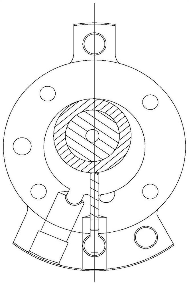
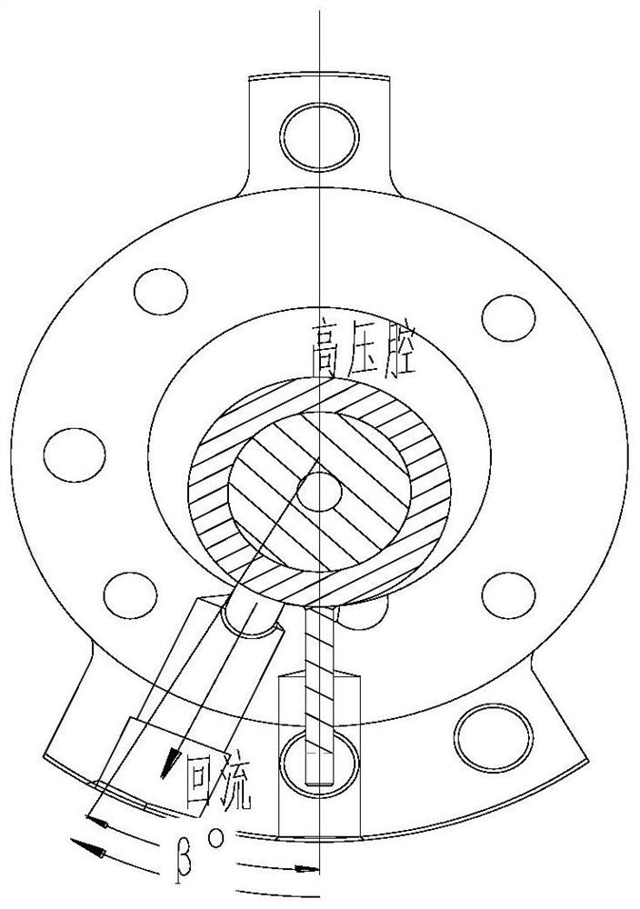
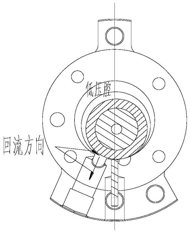
technical field [0001] The invention relates to the technical field of compressors, in particular to a rotor compressor assembly and an air conditioner. Background technique [0002] During the compression process of the existing rotary compressor, the compressor rotor starts from the second circle after the suction end to the front edge angle β of the suction hole, and the refrigerant will cause backflow to a certain extent, resulting in the volumetric efficiency of the pump body. drop, such as figure 2 . [0003] in figure 1 Before the implementation of the scheme of this application, the suction port structure of a cylinder, the suction port is a circular through hole or a through hole with a horn-shaped / U-shaped structure; in order to reduce the problem of suction backflow, the front edge of the suction hole The angle β is generally controlled within 35°. [0004] Such as image 3 , after the compressor exhaust is completed, since the high-pressure gas in the exhau...

Claims


Application Information

Patent Timeline
Patent Type & Authority Applications(China)
IPC IPC(8): F04C18/356F04C29/12
CPCF04C18/3562F04C29/12
Inventor 路为厚李定贤刘达炜韩鑫彭慧明
Owner ZHUHAI LANDA COMPRESSOR
Learn More