Array graph drawing method and system

A graphics drawing and array technology, applied in the field of lithography, can solve the problems of long conversion time, affecting printer work efficiency, low conversion efficiency, etc., and achieve the effect of avoiding time waste, saving drawing time and avoiding material waste

Pending Publication Date: 2022-02-25
HANGZHOU XINNUO MICROELECTRONICS CO LTD
View PDF1 Cites 1 Cited by
  • Summary
  • Abstract
  • Description
  • Claims
  • Application Information

AI Technical Summary

Problems solved by technology

However, in the prior art, Gerber files are converted into bitmap files, and the conversion time is long, and the conversion efficiency is low, which seriously affects the working efficiency of the printer.

Method used


Image

  • Array graph drawing method and system
  • Array graph drawing method and system
  • Array graph drawing method and system

Examples


Embodiment Construction

[0036] The following are specific embodiments of the present invention and the accompanying drawings to further describe the technical solutions of the present invention, but the present invention is not limited to these embodiments.

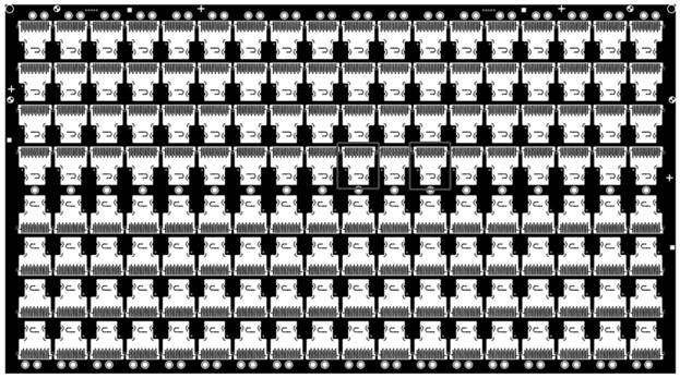
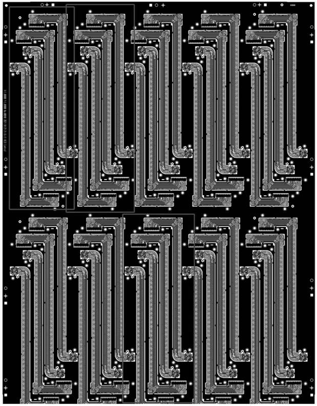
[0037] like figure 1 and figure 2 Shown is the circuit diagram on a conventional PCB board, because there are a large number of repetitive patterns on the circuit on the PCB board (such as figure 1 and figure 2 shown in the red box), and many of them have obvious array characteristics. The graphics are composed of a variety of unpassable units, and there are clear boundaries between units, and the units do not overlap each other. Therefore, the present invention provides A high-efficiency drawing method for array graphics is presented.

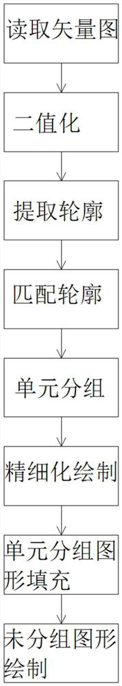
[0038] like image 3 As shown, the method includes the following steps:

[0039] S1; read the vector image file;

[0040] S2, binarizing the vector image file;

[0041] S3, extracting the contour in the...


PUM


Abstract

The invention relates to an array graph drawing method, belongs to the technical field of photoetching, and solves the problem of low graph drawing speed in the prior art. The array graph drawing method comprises the following steps: S1, reading a vector diagram file; S2, carrying out binaryzation on the vector diagram file; S3, extracting a contour in the graph; S4, matching the extracted contours with contours in a template library; S5, performing unit grouping on the matched template and recording the position of each unit; S6, performing refined drawing on the unit grouping graph; and S7, filling the finely drawn unit grouping graph to the corresponding position recorded in the S5. According to the method, the unit array graphs in the vector diagram are extracted by processing the vector diagram, and after the unit array graphs are finely drawn, the unit array graphs are recovered into the bitmaps which can be identified by the photoetching machine in a translation filling mode for exposure of the photoetching machine, so that the drawing time can be greatly saved by utilizing the method.

Description

technical field [0001] The invention belongs to the technical field of photolithography, and relates to a method and system for identifying and positioning patterns based on photolithography positioning, in particular to a method and system for identifying and positioning high-precision out-of-focus patterns. Background technique [0002] Laser direct imaging technology (Laser direct imaging, LDI) is to use the data output by the CAM workstation to directly drive the laser direct imaging device, and perform graphic imaging on the circuit board substrate coated with photoresist (similar to laser photopainting). machine on the polyester base sheet for graphic imaging), and then develop to get the desired graphics, and then etch, remove the film (remove the remaining photoresist), then get the desired pattern on the circuit board Copper conductor graphics up. Obviously, LDI not only reduces many processes such as negative film manufacturing, application, storage and maintenanc...

Claims


Application Information

Patent Timeline
IPC IPC(8): G03F7/20
CPCG03F7/2055G03F7/70383G03F7/70508
Inventor 涂先勤尹鑫吴塞
Owner HANGZHOU XINNUO MICROELECTRONICS CO LTD
Why Eureka
Try Eureka