One-time winding forming method for commutation pole coil of direct-current propulsion motor

A technology for propelling motors and reversing poles, which is applied in the manufacture of motor generators, electrical components, electromechanical devices, etc., and can solve problems such as tearing, difficulty in detachment, and inability of the coil to come out of the mould.

Active Publication Date: 2022-02-25
SHANXI FENXI HEAVY IND
View PDF7 Cites 0 Cited by
  • Summary
  • Abstract
  • Description
  • Claims
  • Application Information

AI Technical Summary

Problems solved by technology

[0002] Because of its wide smooth speed range, large torque and easy control, DC motors are used in occasions that require high speed regulation, such as: rolling mills, trams, electric railway traction, excavation machinery, Textile machinery and ship propulsion and other occasions; the stator part of the DC motor includes the base, the main magnetic pole, the commutation pole, the compensation winding and the brush device, etc., and the rotor part mainly includes the armature, the commutator, the shaft and the bearing and other components; Some of the DC propulsion motors used on ships have a stand-alone capacity of 5000KW, and two motors are used in coaxial series. The method of commutating the loop resistance and reducing the combined potential. The specific measure is to set the commutation pole in the stator of the DC motor. The commutation pole winding coil has the following characteristics: (1) The commutation coil is wound by a copper wire with a rectangular cross section. The length of the rectangular cross-section is 35.5 mm, the width is 22.4 mm, the bending radius is R28 mm, and the total length of the coil is 821 mm; There is a gap of 7mm between the layers to leave space for winding the insulating tape; (2) The coil layers are transposed by twisting the nose, and the layers are formed in an oblique spiral shape, and the left and right are asymmetrical, Continuous three-layer drawer forming; (3) The bending radius is too small, resulting in a large amount of material deformation when the copper wire is bent, and the inner layer is compressed and the outer layer is pulled during bending, which can easily cause tearing; (4) The coil The structure and size are special, and there is no existing technology to learn from; the existing technology, for the processing of similar coils, adopts the method of forming the straight line section and the arc section of the coil in sections, and then forming them by welding. Complete the production of the coil; this conventional production method has the defect that the resistance of the welded connection of the coil will increase significantly, and it cannot meet the requirement of uniform resistance for the commutation coil. In addition, for copper strips with larger cross-sections, During the welding connection, there is still the problem of inability to weld through, which affects the welding strength of the formed coil and greatly reduces the electrical index of the coil, making it unable to play a good role in suppressing the generation of commutation sparks
[0003] Existing different types of motor windings generally use different types of winding molds; windings of the same type and different specifications also need to be replaced with different winding molds; for similar The invented flat copper wire winding with a large cross-section has the characteristics of rapid displacement due to too small bending radius, and at the same time, the bending resistance is relatively large. The tool is tightly combined, so that the coil cannot be smoothly removed from the mold. During the process of pulling out, the shape of the coil needs to be kept intact and protected from damage, which makes it difficult to separate the two; in addition, for the motor For manufacturers, how to reduce the investment cost of tooling and make the designed tooling mold universal and able to meet the winding of coils of the same type but with different specifications has become a difficult problem for designers to solve.

Method used


Image

  • One-time winding forming method for commutation pole coil of direct-current propulsion motor
  • One-time winding forming method for commutation pole coil of direct-current propulsion motor
  • One-time winding forming method for commutation pole coil of direct-current propulsion motor

Examples


Embodiment Construction

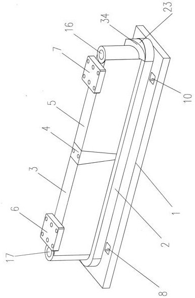
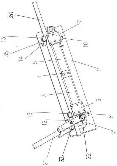
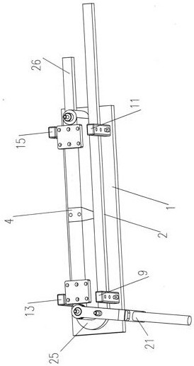
[0036] The present invention is described in detail below in conjunction with accompanying drawing:

[0037] A one-time winding and forming combined tooling for commutating pole coils of DC propulsion motors, including a rectangular base plate 1 and a copper strip 18 for coil winding, and a long barrel-shaped lower mold base 2 is arranged on the rectangular base plate 1 , in the barrel of the elongated barrel-shaped lower mold base 2, a long three-dimensional core block is provided, and the long three-dimensional core block is composed of the left long three-dimensional core block 3, the wedge spliced ​​core block 4 and The long three-dimensional mold core block 5 on the right side is formed by splicing, and the long annular surface at the top of the barrel wall of the elongated barrel-shaped lower mold base 2 is the working table for coil winding, and the left side of the long three-dimensional mold core block 3 on the left is The arc-shaped facade is the forming abutment sur...


PUM


Abstract

The invention discloses a one-time winding forming method for a commutation pole coil of a direct-current propulsion motor. The problem of one-time winding forming of a large-section sudden transposition coil is solved. Like a combined tool, the winding tool is designed into a combined assembly type, and a tool main body part is formed by combining and assembling a rectangular base plate, a long-strip barrel-shaped lower die holder, a long-strip three-dimensional die core, cantilever type pressing blocks on the two sides of the upper end and front and rear plug-in type pressing stand columns and a swing arm type bending wrench, an arc-shaped transposition block with a wedge-shaped inclined plane, an interlayer gap base plate and a jackscrew of a winding straight line edge form a combined accessory for winding the winding. All the components can be partially replaced according to the specifications of winding coils, the whole tool is convenient to assemble, disassemble and combine, and can be suitable for winding the reversing pole coils of various specifications, and the coils can be wound at a time. The tool die is combined, assembly, disassembly and combination are convenient, the tool cost is low, and on-site machining is easy.

Description

technical field [0001] The invention relates to a winding tool for motor windings, in particular to a one-time winding and forming tool for a DC propulsion motor commutation pole coil for a ship and a one-time winding and forming method for a DC propulsion motor commutation pole coil . Background technique [0002] Because of its wide smooth speed range, large torque and easy control, DC motors are used in occasions that require high speed regulation, such as: rolling mills, trams, electric railway traction, excavation machinery, Textile machinery and ship propulsion and other occasions; the stator part of the DC motor includes the base, the main magnetic pole, the commutation pole, the compensation winding and the brush device, etc., and the rotor part mainly includes the armature, the commutator, the shaft and the bearing and other components; Some of the DC propulsion motors used on ships have a stand-alone capacity of 5000KW, and two motors are used in coaxial series. ...

Claims


Application Information

Patent Timeline
Patent Type & Authority Applications(China)
IPC IPC(8): H02K15/04
CPCH02K15/0435H02K15/04
Inventor 聂和林张亚鸽郭永红高旻嵩王晓勤宋建成张蕊莉
Owner SHANXI FENXI HEAVY IND
Why Eureka
Try Eureka