
Method for realizing self power supply of bridge structure monitoring equipment

A technology for monitoring equipment and bridge structures, applied to piezoelectric effect/electrostrictive or magnetostrictive motors, collectors, electric vehicles, etc. Time and other issues, to achieve the effect of improving the efficiency of installation and fixing, increasing the operating space and improving the utilization rate

Active Publication Date: 2022-02-25
WUHAN MUNICIPAL CONSTR GROUP +2
View PDF9 Cites 0 Cited by
  • Summary
  • Abstract
  • Description
  • Claims
  • Application Information

AI Technical Summary

Problems solved by technology

[0003] However, most of the traditional bridge monitoring equipment adopts direct grid power supply or solar power supply. During installation, the staff's hand operation space is relatively limited, which greatly reduces the installation efficiency of monitoring equipment

Method used


Image

  • Method for realizing self power supply of bridge structure monitoring equipment
  • Method for realizing self power supply of bridge structure monitoring equipment
  • Method for realizing self power supply of bridge structure monitoring equipment

Examples


Embodiment Construction

[0036] The present invention will be further described below in conjunction with accompanying drawing:

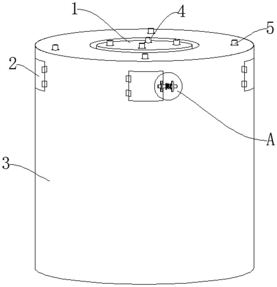
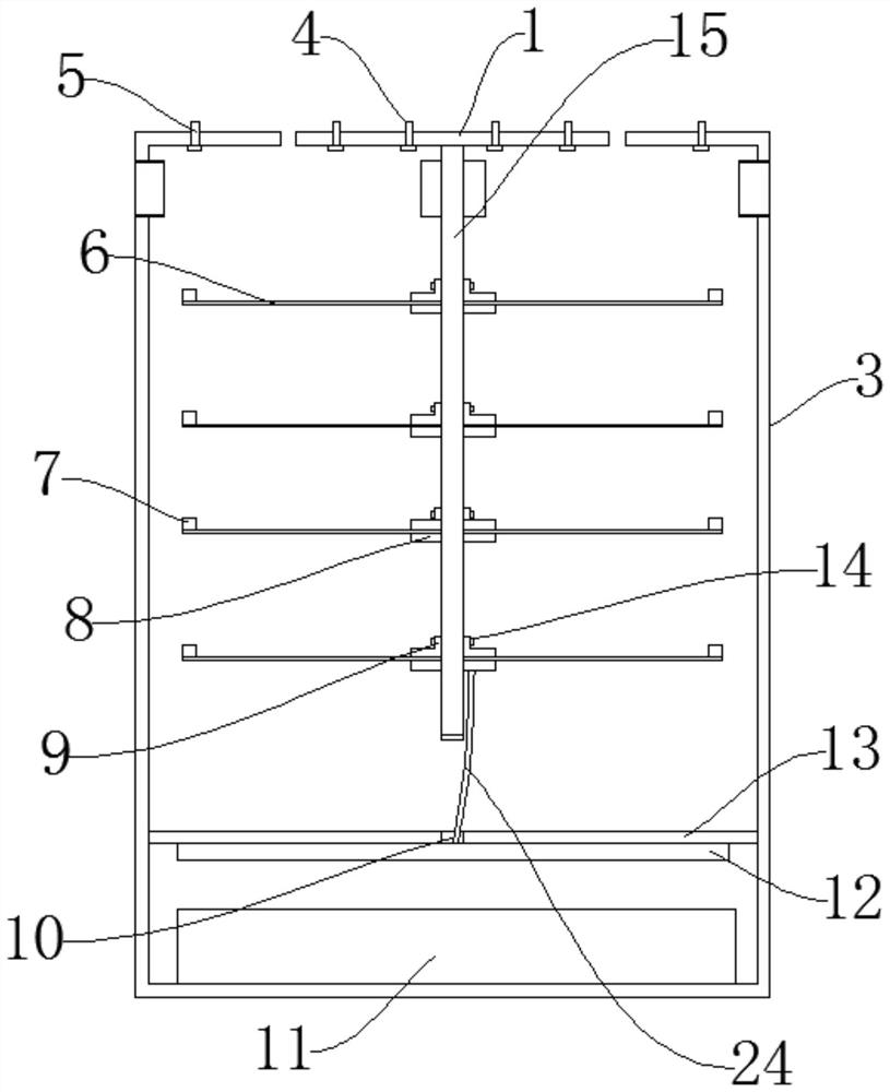
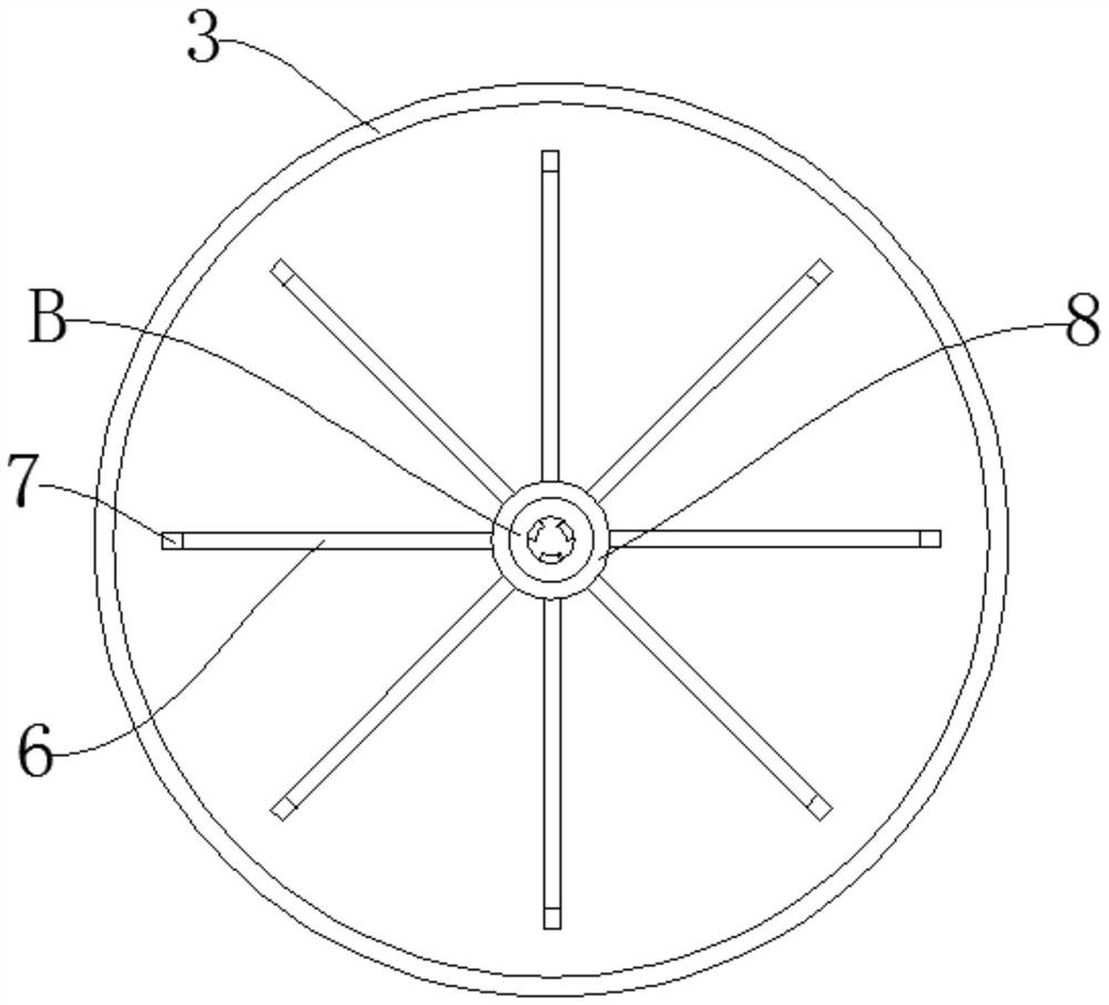
[0037] Such as Figure 1-Figure 6 As shown, a method for realizing self-power supply of bridge structure monitoring equipment includes a vibration base 1, a telescopic shaft 15, a piezoelectric sheet 6 and a rectifying circuit board 12, and the middle part of the bottom end of the vibration base 1 is equipped with the telescopic shaft 15. A telescopic sleeve rod 21 is installed on the peripheral side wall of the telescopic shaft 15. When the length of the telescopic shaft 15 is not adjusted, the fixing seat 8 is mainly connected with the fixed part of the telescopic shaft 15. It is only necessary to adjust the length of the telescopic shaft 15 by sliding the telescopic sleeve rod 21 when the fixed base 8 and the piezoelectric sheet 6 are used. The telescopic sleeve rod 21 can slide along the telescopic shaft 15, thereby To realize the increase in the length of the telescop...


PUM


Abstract

The invention discloses a method for realizing self power supply of bridge structure monitoring equipment. The method comprises a vibration base, a telescopic shaft, a piezoelectric plate and a rectification circuit board. The method has the beneficial effects that through the design of the vibration base, the telescopic shaft, the fixed seat, the piezoelectric plate, the balancing weight, the rectifying circuit board and the capacitor, the piezoelectric plate can swing by utilizing vibration of the bridge main body so that electric energy is generated and finally stored in the capacitor to be used by external monitoring equipment; not only can full conversion and utilization of energy be realized and the utilization rate of the energy be effectively improved, but also the device does not need additional wiring in use and meets the requirement of normal use of external monitoring equipment in a power shortage zone; and through the design of a movable door plate, a limiting ring, a limiting rod, a spring and a fixing ring, the operation space of the hand of a worker can be effectively increased when the box body is installed, rapid screwing of the worker is facilitated, and therefore the overall installing and fixing efficiency of the device is improved.

Description

technical field [0001] The invention relates to the technical field of self-generating devices, in particular to a method for realizing self-power supply of bridge structure monitoring equipment. Background technique [0002] During the use of the bridge, in order to ensure the safety of driving on the bridge and the service life of the bridge, it is often necessary to install monitoring equipment on the bridge. [0003] However, most of the traditional bridge monitoring equipment adopts direct grid power supply or solar power supply. During installation, the staff's hand operation space is relatively limited, which greatly reduces the installation efficiency of monitoring equipment. Contents of the invention [0004] The object of the present invention is to provide a method for realizing self-power supply of bridge structure monitoring equipment in order to solve the above problems. [0005] The present invention achieves the above object through the following technica...

Claims


Application Information

Patent Timeline
Patent Type & Authority Applications(China)
IPC IPC(8): H02N2/18H02J7/32
CPCH02N2/186H02N2/181H02J7/32H02J2207/50
Inventor 房瑞伟杨斯微鞠鹏飞吴慧秦泽翔宋振辉乔威芩王顺林李晓东赵军丽
Owner WUHAN MUNICIPAL CONSTR GROUP
Learn More