Intelligent street lamp based on Internet of Things
A technology of smart street lights and the Internet of Things, applied in the field of smart street lights based on the Internet of Things, can solve the problems of poor practicability of street lights, damage to charging piles, hidden dangers to the life safety of maintenance personnel, etc., so as to facilitate installation, disassembly and replacement, and ensure life safety. , the effect of improving usability
- Summary
- Abstract
- Description
- Claims
- Application Information
AI Technical Summary
Problems solved by technology
Method used
Image
Examples
Embodiment 1
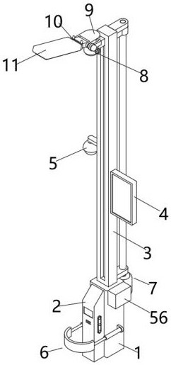
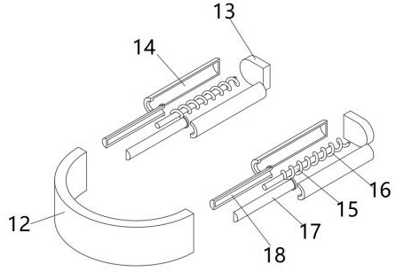
[0034] like figure 2As shown, in this embodiment, in order to prevent the vehicle from causing damage to the charging pile 2 when charging, the side walls on both sides of the base 1 are respectively fixed with a fixed plate 13, and the front end of the fixed plate 13 is fixed with a fixed cylinder 14 , the bottom of the fixed cylinder 14 is fixedly equipped with a first fixed rod 15, the first fixed rod 15 is covered with a first compression spring 16, and the rear end of the first compression spring 16 is fixedly installed on the bottom of the fixed cylinder 14, The rear end of the buffer column 17 is provided with a buffer groove 18, the buffer column 17 is movably installed in the cylinder of the fixed cylinder 14, the first fixed rod 15 is interspersed and installed in the buffer groove 18, and the front end of the first compression spring 16 is fixedly installed on the buffer column 17, the front end of the buffer column 17 is fixedly installed on the rear end side wall...
Embodiment 2
[0036] like Figure 3-4 As shown, in this embodiment, in order to prevent maintenance personnel from climbing up to maintain the street lamp body 11 and ensure the safety of maintenance personnel, a vertical opening 19 is provided on the front wall of the light pole 3, and the vertical opening 19 The two sides of the inner wall of the notch are respectively fixed with track plates 20, and the upper and lower ends of the rear wall of the light pole 3 are respectively fixed with fixed blocks 25, and the top surface of the fixed block 25 is provided with a first rotation groove 26, and the two ends of the screw rod 23 The first rotating block 24 is fixedly installed respectively, and the first rotating block 24 is movably installed in the first rotating groove 26, the servo motor 21 is fixedly installed on the rear wall of the base 1, and the top of the servo motor 21 is movably installed with a motor rotating shaft. head 22, and the top surface of the motor rotor 22 is fixedly i...
Embodiment 3
[0038] like Figure 5 As shown, in this embodiment, in order to fix the second motor 42, side blocks 31 are respectively fixedly installed on the side walls on both sides of the two half-ring blocks 30, and through holes 32 are opened on the side blocks 31, The rear wall of the half ring block 30 of the rear end is fixedly installed on the front wall of the support rod 28, and the bolt 33 is inserted and installed in the symmetrical through hole 32, and the second nut 34 is threaded on the rear end of the bolt 33, and the second motor 42 is placed between the symmetrical half-ring blocks 30, then the bolt 33 is inserted into the through hole 32 provided on the front and rear symmetrical side block 31, and finally the second nut 34 is screwed onto the rear end of the bolt 33 to This fixes the second motor 42 between the half-ring blocks 30 .
PUM
 Abstract
Description
Claims
Application Information
 - R&D
- Intellectual Property
- Life Sciences
- Materials
- Tech Scout
- Unparalleled Data Quality
- Higher Quality Content
- 60% Fewer Hallucinations
Browse by: Latest US Patents, China's latest patents, Technical Efficacy Thesaurus, Application Domain, Technology Topic, Popular Technical Reports.
© 2025 PatSnap. All rights reserved.Legal|Privacy policy|Modern Slavery Act Transparency Statement|Sitemap|About US| Contact US: help@patsnap.com


