A processing and conveying system for medical vehicle parts and its use method

A technology for conveying systems and parts, applied in the field of processing and conveying systems for medical vehicle parts, can solve the problems of huge manpower consumption, low handling efficiency, heavy frame weight, etc., and achieve good cooling effect, low cost and precise cooling effect

Active Publication Date: 2022-04-15
常州江苏大学工程技术研究院 +1
View PDF0 Cites 0 Cited by
  • Summary
  • Abstract
  • Description
  • Claims
  • Application Information

AI Technical Summary

Problems solved by technology

[0003] At the same time, the welded frame needs to be placed and collected. At present, the welded frame is manually transported away from the conveyor line. Due to the heavy weight of the frame, a huge amount of manpower is required, and the handling efficiency is low.

Method used


Image

  • A processing and conveying system for medical vehicle parts and its use method
  • A processing and conveying system for medical vehicle parts and its use method
  • A processing and conveying system for medical vehicle parts and its use method

Examples


Embodiment 1

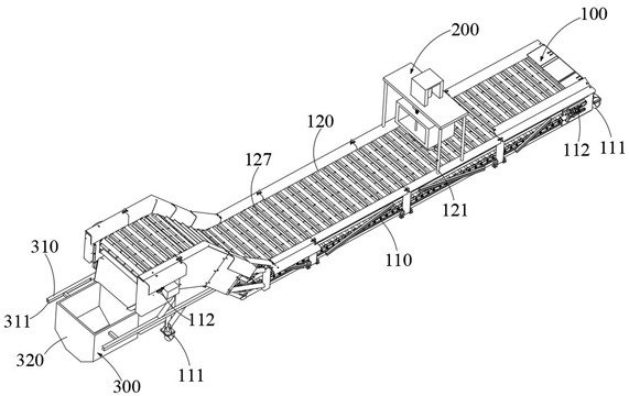
[0050] Such as Figure 1~7As shown, a medical vehicle parts processing delivery system includes a delivery mechanism 100, a welding mechanism 200 arranged at the upper end of the delivery mechanism 100 and a recovery mechanism 300 arranged at one end of the delivery mechanism 100, and the recovery mechanism 300 It includes a fixed rod 310 arranged at one end of the conveying mechanism 100, a recovery box 320 slidably arranged on the fixed rod 310, and several sieve holes 321 provided in the recovery box 320. The length of the fixed rod 310 is A slot 311 is opened in the direction, and an insert 322 adapted to the slot 311 is opened on the side wall of the recovery box 320, wherein the insert 322 is slidably arranged in the slot 311, so that Replace the recovery box 320 .

[0051] Conveying mechanism 100

[0052] The conveying mechanism 100 is suitable for conveying the object to be welded to the welding mechanism 200 , and then conveying the object to be welded to the recove...

Embodiment 2

[0064] On the basis of Embodiment 1, this Embodiment 2 also provides a medical vehicle parts processing and conveying system and its use method, wherein a medical vehicle parts processing and conveying system is the same as Embodiment 1, and will not be repeated here. . A specific method of using a medical vehicle parts processing and conveying system is as follows:

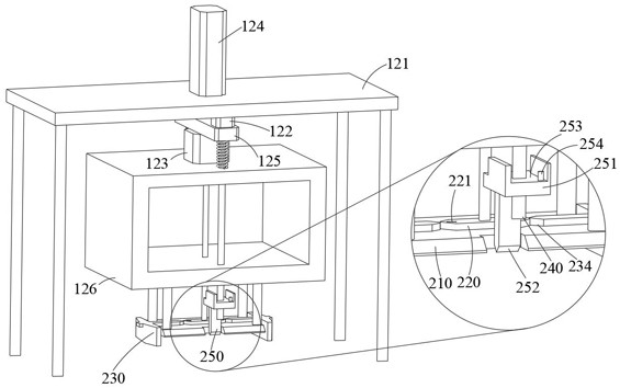
[0065] S1. The conveyor belt 120 transports the object to be welded to the bottom of the welding mechanism 200, and the crimping plate 210 moves downward to compress the object to be welded;

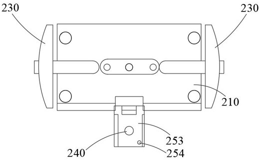
[0066] S2. When the waist-shaped plate 220 rotates until the waist-shaped plate 220 pushes the shear plate 250 to squeeze the air bag 1, the air jet from the blowing port is suitable for cleaning the redundant fins on the object to be welded , at the same time, the extrusion plate 230 moves toward the waist plate 220 to clamp and fix the object to be welded, and the shear plate 250 moves downward to remove excess fins on t...


PUM


Abstract

The present invention relates to the field of conveying technology, in particular to a processing and conveying system for medical vehicle parts and its use method, a conveying mechanism, a welding mechanism arranged at the upper end of the conveying mechanism, and a recovery mechanism arranged at one end of the conveying mechanism. The recovery mechanism includes a fixed rod arranged at one end of the conveying mechanism, a recovery box slidingly arranged on the fixed rod, and a number of sieve holes provided in the recovery box. The side wall of the recycling box is provided with an inserting block adapted to the slot, wherein the inserting block is slidably arranged in the slot so as to replace the recycling box. In the present invention, the recovery box is plugged into the slot, and then the processed vehicle frame is transported into the recovery box through a conveyor belt, and finally the recovery box is transported away by a delivery trolley, and then a new recovery box is replaced.

Description

technical field [0001] The invention relates to the field of conveying technology, in particular to a processing and conveying system for parts of a medical vehicle and a method for using the same. Background technique [0002] Medical equipment refers to instruments, equipment, utensils, materials or other items used alone or in combination for the human body, including the required software. Medical equipment is the most basic element of medical treatment, scientific research, teaching, institutions, and clinical disciplines, including professional Medical equipment, including household medical equipment, medical vehicles play an important role in medical equipment, whether the nursing staff to change the patient's dressing, or the medical staff to the patient's medical treatment, it is necessary for the medical vehicle to carry the medical equipment needed for medical treatment. Devices and medicines. Such as Figure 7 As shown, a frame with fins needs to be used on the ...

Claims


Application Information

Patent Timeline
Patent Type & Authority Patents(China)
IPC IPC(8): B23K37/00B08B5/02B23D31/00B23P15/00B23P23/04
CPCB23K37/00B23K37/003B08B5/02B23D31/00B23P23/04B23P15/00
Inventor 金磊赵建林黄挺刘新刚周逸文余金明
Owner 常州江苏大学工程技术研究院
Why Eureka
Try Eureka