Long-period high-precision polishing mechanism of lens polishing machine

A lens polishing and polishing mechanism technology, which is applied in the field of lens polishing machines, can solve the problems of misalignment of the pressure mechanism, excessive polishing of parts, and insufficient polishing effect, so as to ensure the pressing accuracy, improve the polishing accuracy, and improve the stability and reliability of the installation. Effect

Pending Publication Date: 2022-03-01
江西吉铖光电有限公司
View PDF0 Cites 0 Cited by
  • Summary
  • Abstract
  • Description
  • Claims
  • Application Information

AI Technical Summary

Problems solved by technology

Therefore, it can be seen that the pressing position of the pressure shaft also determines the precision of the grinding. When the pressing position of the upper pressure shaft deviates, the position of the lens on the grinding tool is also prone to shifting, and the shifting will cause the position Too much polishing in some places, not enough polishing in some places
[0004] The installation of the pressure shaft is carried out through the pressure mechanism. The pressure mechanism in the prior art is installed and fixed on the frame through the installation structure of screws and fixed blocks. If it is shifted, the position of the pressure mechanism will be misaligned, which will lead to a decrease in polishing accuracy.

Method used


Image

  • Long-period high-precision polishing mechanism of lens polishing machine
  • Long-period high-precision polishing mechanism of lens polishing machine
  • Long-period high-precision polishing mechanism of lens polishing machine

Examples


Embodiment Construction

[0033] The present invention will be further described in detail below in conjunction with the embodiments and the accompanying drawings, but the embodiments of the present invention are not limited thereto.

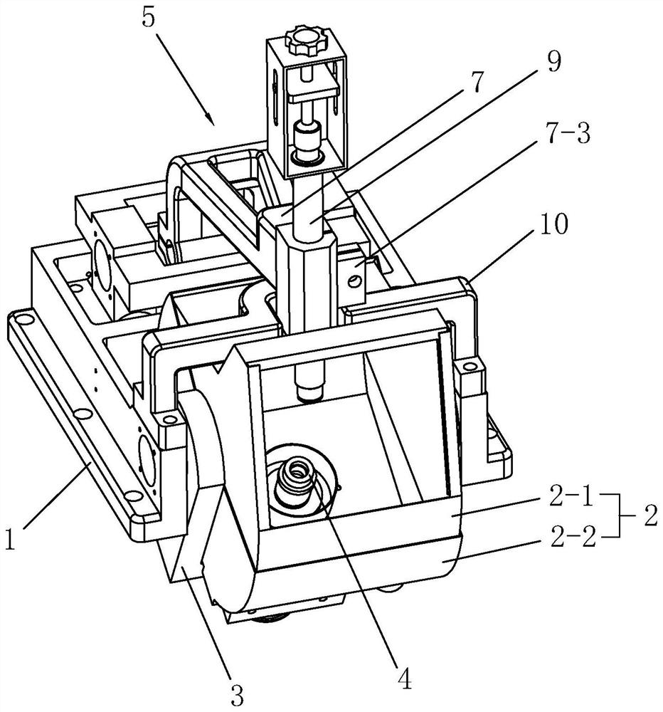
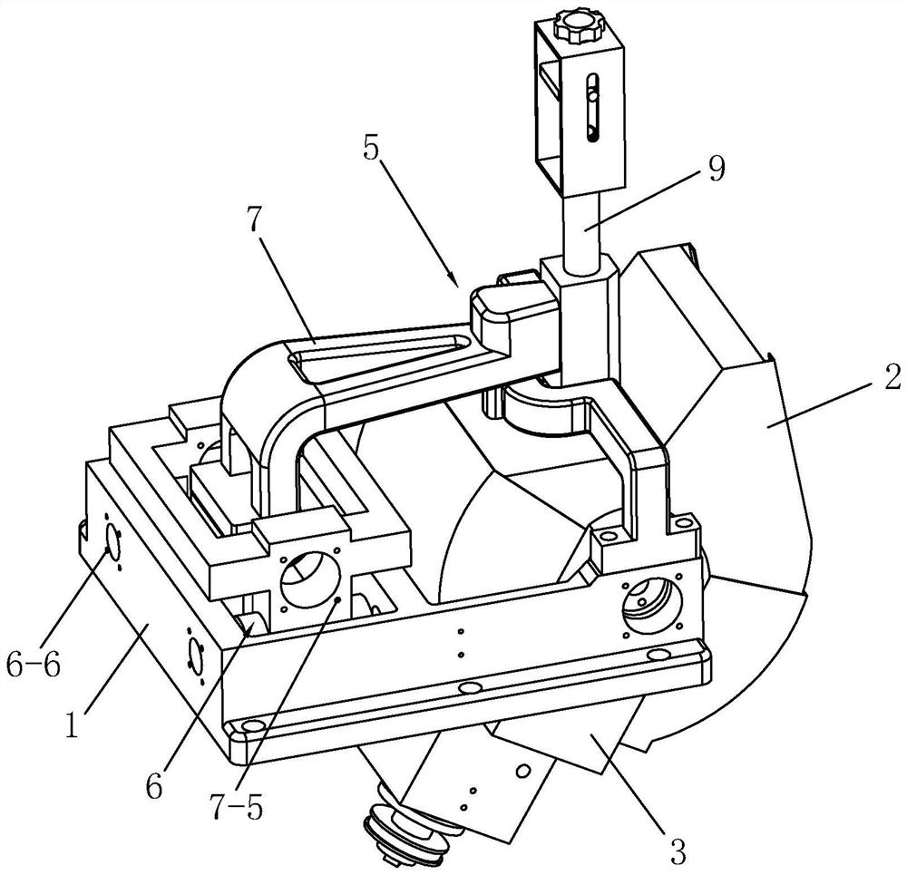
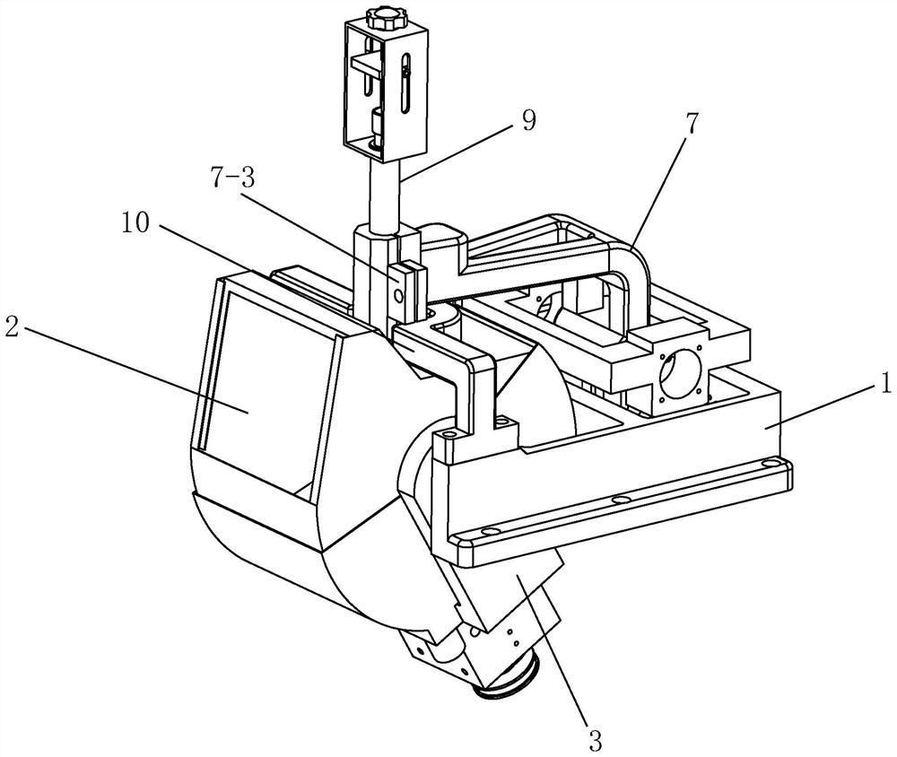
[0034] A long-period high-precision polishing mechanism for a lens polishing machine, combined with Figure 1-Figure 5 As shown, a long-cycle high-precision polishing mechanism of a lens polishing machine includes a base 1, a bucket 2, a swing arm 3, a spindle 4, and a pressure mechanism 5. The base 1 is used to install the whole on any external rack Above, the swing arm 3 is installed on one end of the base 1 and can swing around its installation axis. The main shaft 4 is installed in the hole of the swing arm 3 and placed inside the water bucket 2. The water bucket 2 is divided into a fixed bucket 2- 1 and the swing bucket 2-2, the upper side of the fixed bucket is fixed on the lower side of the bridge frame 10, the two sides and the lower side of the swing bucket 2-2 ...


PUM


Abstract

The invention relates to the technical field of lens polishing machines, and discloses a long-period high-precision polishing mechanism of a lens polishing machine, which solves the technical problem of how to improve the installation stability and reliability of a pressure mechanism at present, and comprises a base, a water bucket, a swing arm, a main shaft and a pressure mechanism, the swing arm is installed at one end of the base and can swing with an installation shaft of the swing arm as a shaft core, the main shaft is installed in a swing arm hole and arranged in the water bucket, the water bucket is divided into a fixed bucket body and a swing bucket body, the upper side of the fixed bucket body is fixed to the lower side of the bridge, the two sides and the lower side of the swing bucket body are fixed to the inner side face of the swing arm, and the pressure mechanism is installed on the base. According to the technical scheme, the mounting stability of the pressure arm is improved through the mounting structure of the X-axis holding hole and the Y-axis holding hole, and mounting errors similar to screw loosening caused by long-period equipment machining are basically avoided, so that the purpose of high-precision polishing machining is achieved.

Description

technical field [0001] The invention relates to the technical field of lens polishing machines, more specifically, it relates to a long-period high-precision polishing mechanism of a lens polishing machine. Background technique [0002] Lens polishing machine is divided into upper swing machine and lower swing machine in the industry. The principle of grinding and polishing is similar. It is mainly used for lens grinding of high-end instruments, such as optical lenses of microscopes and other instruments. [0003] Existing polishing machine mainly comprises frame, base, grinding tool, pressure shaft and the pressure mechanism that pressure shaft is installed, and present pressure mechanism is installed on the frame, and the station notch that is used for polishing is installed on the frame, and base is as for In the notch of the station, the abrasive tool is installed on the base. The lens to be polished is placed on the abrasive tool. The upper part of the lens is pressed b...

Claims


Application Information

Patent Timeline
Patent Type & Authority Applications(China)
IPC IPC(8): B24B13/00B24B13/005B24B41/04B24B41/02B24B41/00
CPCB24B13/00B24B13/0055B24B41/04B24B41/02B24B41/00
Inventor 邱家铖邱忠杰
Owner 江西吉铖光电有限公司
Why Eureka
Try Eureka