
Conductive film attaching equipment

A conductive film and attachment technology, which is applied to household appliances, other household appliances, and household components, etc., can solve the problems of attachment failure, tearing of the conductive film, and low bonding yield between the conductive film and the liquid crystal display.

Active Publication Date: 2022-03-01
惠州深科达智能装备有限公司
View PDF10 Cites 2 Cited by
  • Summary
  • Abstract
  • Description
  • Claims
  • Application Information

AI Technical Summary

Problems solved by technology

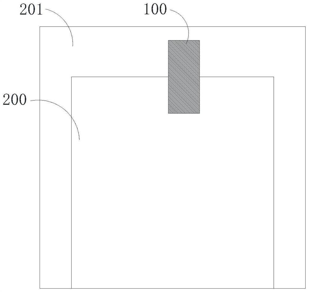
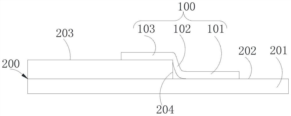
Therefore, when attaching the pressure head to attach the conductive film to the liquid crystal display and the metal backplane, if the length of the conductive film at the step is relatively large, it is easy to cause the conductive film to be stuck at the step or Wrinkles are formed on the metal backplane near the step or on the liquid crystal display near the step. If the length of the conductive film at the step is small, it is easy to cause the conductive film to be attached to the conductive film on the liquid crystal display during the attachment process. The part and the part of the conductive film attached to the metal backplane will pull each other, which will cause the conductive film to tear and cause the attachment to fail, making the bonding yield of the conductive film and the liquid crystal display lower.

Method used


Image

  • Conductive film attaching equipment
  • Conductive film attaching equipment
  • Conductive film attaching equipment

Examples


Embodiment Construction

[0085] The technical solutions in the embodiments of the present invention will be clearly and completely described below with reference to the accompanying drawings in the embodiments of the present invention. Obviously, the described embodiments are only a part of the embodiments of the present invention, but not all of the embodiments. Based on the embodiments of the present invention, all other embodiments obtained by those of ordinary skill in the art without creative efforts shall fall within the protection scope of the present invention.

[0086]In the present invention, the terms "upper", "lower", "left", "right", "front", "rear", "top", "bottom", "inner", "outer", "vertical" The orientation or positional relationship indicated by , "horizontal", "horizontal", "longitudinal", etc. is based on the orientation or positional relationship shown in the drawings. These terms are primarily used to better describe the invention and its embodiments, and are not intended to limi...


PUM


Abstract

The invention discloses conductive film attaching equipment, and relates to the technical field of automatic machinery, the conductive film attaching equipment comprises a primary attaching module, a pre-pressing module and a pressure maintaining module, the primary attaching module is used for attaching the edge, away from a second part, of a first part of a conductive film to the upper surface of the first edge of a metal backboard; the pre-pressing module is located at the downstream of the initial pasting module, and the pre-pressing module is used for integrally pasting the first part of the conductive film to the metal backboard; the pressure maintaining module is located on the downstream of the pre-pressing module and used for enabling the third part of the conductive film to be attached to the upper surface of the first edge of the display module and enabling the second part of the conductive film to be attached to the side wall of the first edge of the display module. The conductive film attaching equipment is used for attaching a conductive film and a display module. According to the conductive film attaching equipment, the attaching precision of the conductive film and the display module can be improved, so that the attaching quality of the conductive film and the display module is improved.

Description

technical field [0001] The present application relates to the technical field of automated machinery, and in particular, to a device for attaching a conductive film. Background technique [0002] Liquid crystal displays are widely used in various electronic products, such as mobile phones and computer monitors. In order to prevent the existence of static charge on the casing of the liquid crystal display and at the same time make the liquid crystal display have a lower weight, the casing of the liquid crystal display is generally made of plastic. During the production and working process of liquid crystal display, static charge will accumulate and store on its surface, and the plastic casing cannot release the accumulated static charge. Therefore, by attaching the metal backplane to the back of the liquid crystal display, and then electrically connecting the liquid crystal display and the metal backplane with a conductive film, the static charge is released in time. [000...

Claims


Application Information

Patent Timeline
IPC IPC(8): B29C63/00B29C63/02B29L31/34
CPCB29C63/0004B29C63/0052B29C63/0013B29C63/02B29L2031/3475
Inventor 黄奕宏方明登秦超尹国伟韩宁宁庄庆波张新明
Owner 惠州深科达智能装备有限公司
Learn More