Wear-resistant flexible unwinding trolley for high-speed steel machining

A high-speed steel, wear-resistant technology, applied in the direction of trolleys, motor vehicles, coiled strips, etc., can solve the limitation of small steel movement, the stability and safety of equipment operation are not better guaranteed, and the operation effect is not flexible enough and other issues, to achieve the effect of guaranteeing fixed stability and safety, improving operating effect and operating status, moving efficiency and stability guarantee

Pending Publication Date: 2022-03-01
江苏伟建工具科技有限公司
View PDF0 Cites 0 Cited by
  • Summary
  • Abstract
  • Description
  • Claims
  • Application Information

AI Technical Summary

Problems solved by technology

[0003] Most of the unwinding devices are rail-type, which is not easy to move during use, and the operation effect is not flexible enough. There is no more flexible operation effect for lifting small steel products, and the movement of small steel products is relatively limited.
[0004] The existing unwinding device for high-speed steel processing is inconvenient to move when in use, and the operating flexibility is poor. There is no better guarantee for the lifting effect of the small just now, and there is no more comprehensive solution to the wear and tear of the lifting during use. There is no better guarantee for the operation stability and safety of the equipment

Method used


Image

  • Wear-resistant flexible unwinding trolley for high-speed steel machining
  • Wear-resistant flexible unwinding trolley for high-speed steel machining
  • Wear-resistant flexible unwinding trolley for high-speed steel machining

Examples


Embodiment Construction

[0031] The following will clearly and completely describe the technical solutions in the embodiments of the present invention with reference to the accompanying drawings in the embodiments of the present invention. Obviously, the described embodiments are only some, not all, embodiments of the present invention. Based on the embodiments of the present invention, all other embodiments obtained by persons of ordinary skill in the art without making creative efforts belong to the protection scope of the present invention.

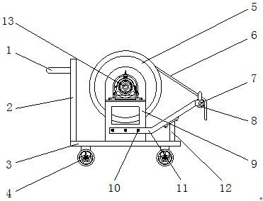
[0032] see Figure 1-8 , a wear-resistant flexible unwinding trolley for high-speed steel processing, including a handle 1, one side of the handle 1 is fixedly connected with a side plate 2, the bottom of the side plate 2 is fixedly connected with a bottom plate 3, and the bottom of the bottom plate 3 is fixed A roller 4 is connected, and a mounting plate 9 is fixedly connected to the top of the bottom plate 3 .

[0033] The front of mounting plate 9 is fixed...


PUM


Abstract

The invention relates to the technical field of steel processing unwinding devices, and discloses a wear-resistant flexible unwinding trolley for high-speed steel processing, which comprises a grip, a side plate is fixedly connected to one side of the grip, a bottom plate is fixedly connected to the bottom of the side plate, rollers are fixedly connected to the bottom of the bottom plate, and a mounting plate is fixedly connected to the top of the bottom plate. The front face of the mounting plate is fixedly connected with a gear motor, the back face of the mounting plate is fixedly connected with a winding mechanism, and the outer wall of the winding mechanism is movably connected with a steel cable. According to the wear-resistant flexible unwinding trolley for high-speed steel machining, when the wear-resistant flexible unwinding trolley is used, a grip is held by a hand to push a side plate, a bottom plate is driven to move when the side plate is pushed, and when the bottom plate moves, rolling wheels conduct sliding work and auxiliary moving work, and the moving stability can be more effectively guaranteed through auxiliary moving of the rolling wheels; and the moving efficiency and the stability of the equipment are better guaranteed.

Description

technical field [0001] The invention relates to the technical field of unwinding devices for steel processing, in particular to a wear-resistant flexible unwinding trolley for high-speed steel processing. Background technique [0002] When steel processing is in use, an unwinding device is needed to move the steel. It can effectively ensure the safety of steel lifting and better ensure the efficiency of steel processing. [0003] Most of the unwinding devices are rail-type, which is not easy to move when in use, and the operation effect is not flexible enough. There is no more flexible operation effect for lifting small steel products, and the movement of small steel products is relatively limited. [0004] The existing unwinding device for high-speed steel processing is inconvenient to move when in use, and the operating flexibility is poor. There is no better guarantee for the lifting effect of the small just now, and there is no more comprehensive solution to the wear and...

Claims


Application Information

Patent Timeline
Patent Type & Authority Applications(China)
IPC IPC(8): B65H16/06B65H16/10B65H49/20B65H49/34B65H71/00B62B3/10B62B5/06
CPCB65H16/06B65H16/103B65H49/20B65H49/34B65H71/00B62B3/104B62B5/06B65H2701/1133B65H2701/173B65H2701/35
Inventor 鲁荣年
Owner 江苏伟建工具科技有限公司
Why Eureka
Try Eureka