
Drill rod lower pipe positioning device for mine exploration construction and implementation method of drill rod lower pipe positioning device

A technology of positioning device and drill pipe, applied in the direction of drill pipe, drill pipe, casing, etc., can solve the problem of inconvenient threaded connection, etc., and achieve the effect of convenient threaded connection

Inactive Publication Date: 2022-03-01
刘永丽
View PDF0 Cites 0 Cited by
  • Summary
  • Abstract
  • Description
  • Claims
  • Application Information

AI Technical Summary

Problems solved by technology

[0003] In the prior art, the exploration of the ore deposit needs to drill the probe tube into the ground for exploration, but when drilling the tube, it is necessary to clamp and position the upper end of the probe tube that has been inserted into the ground, and to perform auxiliary positioning on the lower end of the probe tube to be connected , so that it is convenient to carry out threaded connection between the two groups of probe tubes, but the existing positioning device for the probe tubes cannot realize the positioning and fixing of the probe tubes well, and it is inconvenient to carry out threaded connection

Method used


Image

  • Drill rod lower pipe positioning device for mine exploration construction and implementation method of drill rod lower pipe positioning device
  • Drill rod lower pipe positioning device for mine exploration construction and implementation method of drill rod lower pipe positioning device
  • Drill rod lower pipe positioning device for mine exploration construction and implementation method of drill rod lower pipe positioning device

Examples


Embodiment approach

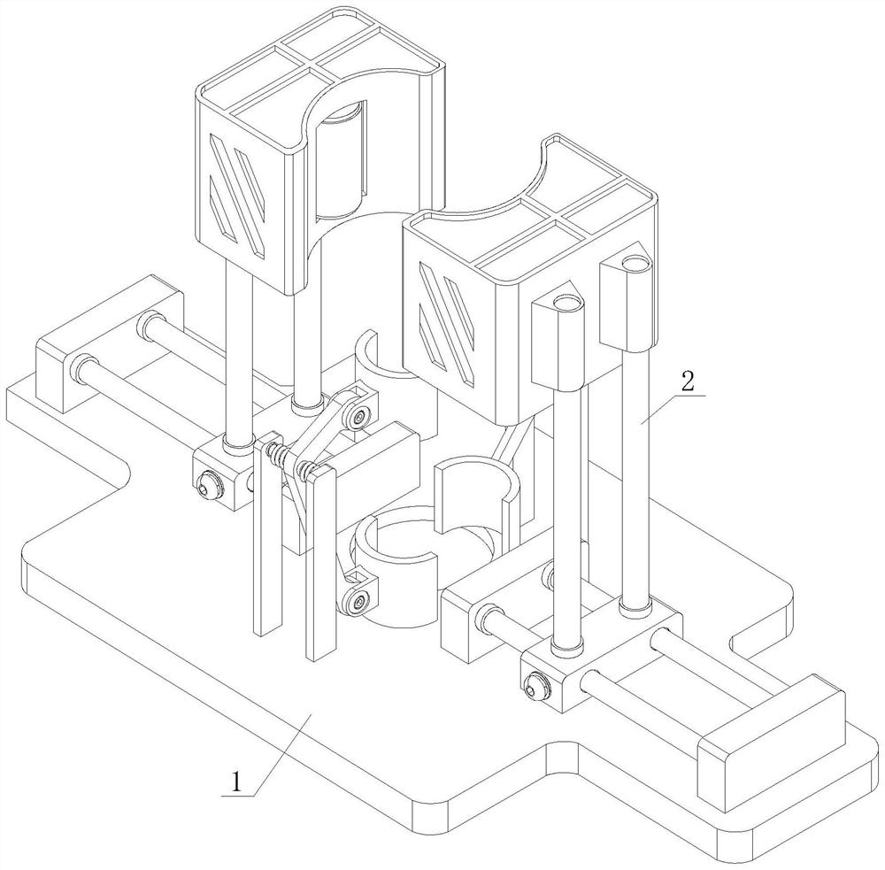
[0035] The present invention provides another technical solution: a method of implementing a drill pipe for a mining exploration construction drill pipe, including the following steps:

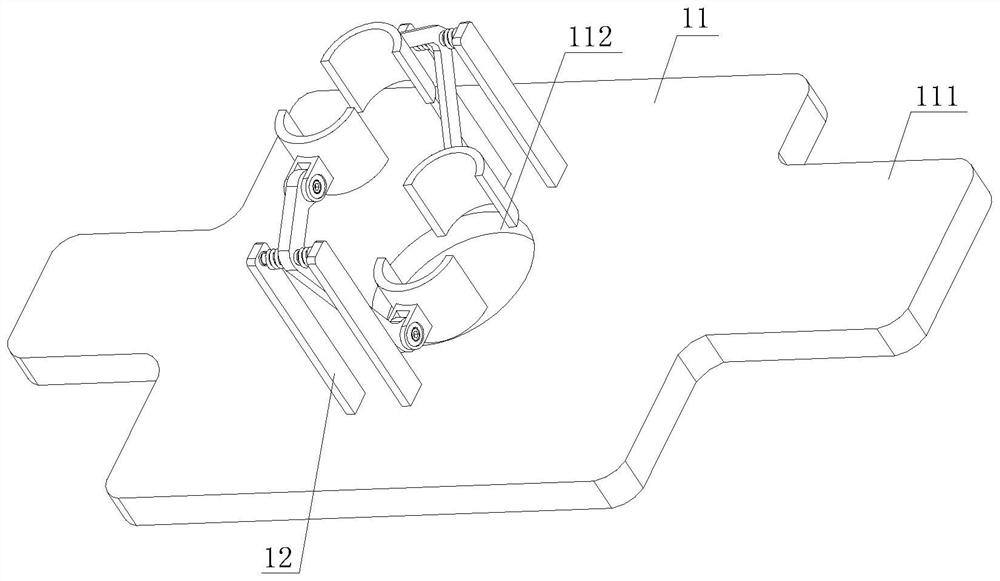
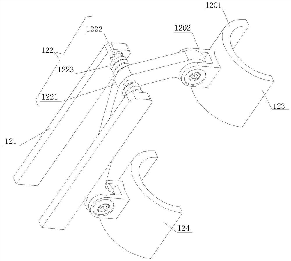
[0036] S01: The upper end of the probe that has been inserted into the underground is fixed between the lower positioning sheet 124;

[0037] S02: Probabilizing tube extrapolates the lower positioning sheet 124, the rod 1221 is rotated, and the upper end of the two groups of curved rods 1221 is collected inward, and the lower end to the detection tube is adjusted;

[0038] S03: Move the moving block 213 on the guide post 212, adjust the distance between the two sets of the auxiliary rotation mechanism 2 set, and the upper end of the detection tube is positioned;

[0039] S04: The start drive motor 2202 drives the rubber surface rotation shaft 2204 to rotate, and the rubber surface rotation shaft 2204 drives the tube to be connected to complete the thread connection between the probe.

[0040] Work...


PUM


Abstract

The invention discloses a drill pipe down-pipe positioning device for mine exploration construction and further discloses an implementation method of the drill pipe down-pipe positioning device for mine exploration construction, the drill pipe down-pipe positioning device for mine exploration construction comprises a supporting and positioning mechanism and an auxiliary rotating mechanism, and the auxiliary rotating mechanism is fixedly arranged on the supporting and positioning mechanism; the upper end of an exploring tube inserted into the ground is fixedly clamped between the lower positioning pieces, the exploring tube pushes the lower positioning pieces outwards towards the two sides due to the fact that the length of the lower ends of the bent rods is larger than that of the upper ends of the bent rods, the bent rods rotate, the upper ends of the two sets of bent rods are folded inwards, and auxiliary limiting is conveniently conducted on the lower end of the exploring tube to be connected; according to the positioning and clamping assembly, the to-be-connected exploring tube and the exploring tube inserted into the ground are prevented from deviating, the upper end of the exploring tube inserted into the ground can be clamped and positioned, the lower end of the to-be-connected exploring tube can be limited in an auxiliary mode, and threaded connection between the exploring tubes is more convenient.

Description

Technical field [0001] The present invention relates to the field of mineral exploration technologies, and is specifically a mine exploration, drill rod, pipe positioning device and its implementation method. Background technique [0002] Mineral exploration, through the census, detailed investigation, which has identified deposits with industrial value, to apply effective exploration techniques and methods, and provide reliable ore reserves and the necessary geological, technical and economic data for mine design. Also known as the depression exploration. [0003] The exploration of the deposit in the prior art exploration needs to be explored underground, but in the drill pipe, it is necessary to clamping the upper end of the inserted exploration, and the lower end of the detection tube to be connected. The two sets of probes are easily threaded, while the existing positioning device for the probe is unable to achieve the positioning of the probe, and is inconvenient for thread...

Claims


Application Information

Patent Timeline
Patent Type & Authority Applications(China)
IPC IPC(8): E21B7/04E21B19/24E21B41/00
CPCE21B7/04E21B19/24E21B41/00
Inventor 刘永丽
Owner 刘永丽
Learn More