Maneuvering target ISAR self-focusing imaging method based on deep learning
A technology of maneuvering targets and imaging methods, applied in the field of radar, can solve the problems of noise interference and low resolution of ISAR images, and achieve the effect of high resolution
- Summary
- Abstract
- Description
- Claims
- Application Information
AI Technical Summary
Problems solved by technology
Method used
Image
Examples
specific Embodiment approach 1
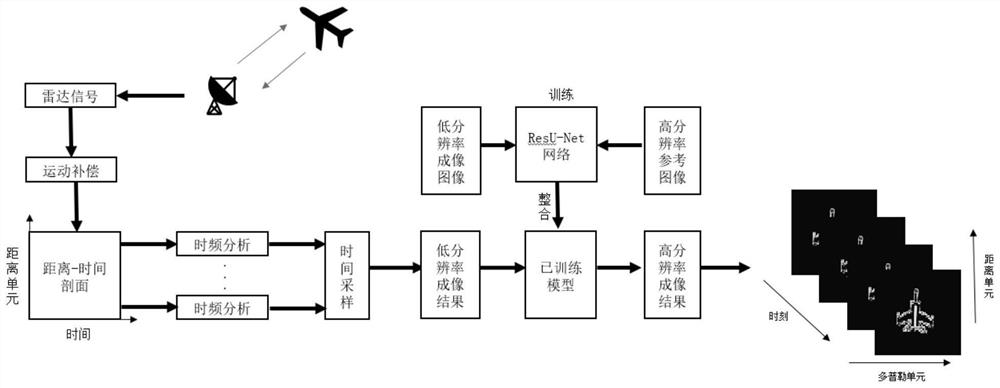
[0040] Specific implementation mode 1: In this implementation mode, a specific process of an ISAR self-focusing imaging method for maneuvering targets based on deep learning is as follows:
[0041] Step 1. Set the maximum number of cycles T, T≥2;
[0042] Set the number of cycles t=1, set the initial value of the maneuvering target form and motion parameters, and the maneuvering target motion parameters include angular velocity ω and angular acceleration γ;
[0043] Step 2, the signal source transmits the LFM signal, the LFM signal is received by the radar after being reflected by the maneuvering target, the received signal is an echo, and the obtained echo is dechirped to obtain the processed echo;
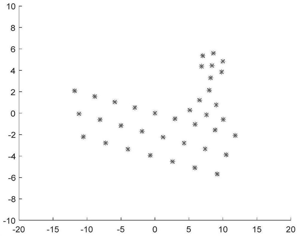
[0044] The maneuvering target form is composed of scattered points;
[0045] The maneuvering target is composed of randomly generated scatter points;
[0046] Perform range compression on the processed multiple echoes to obtain multiple one-dimensional range images (to obtain r...
specific Embodiment approach 2
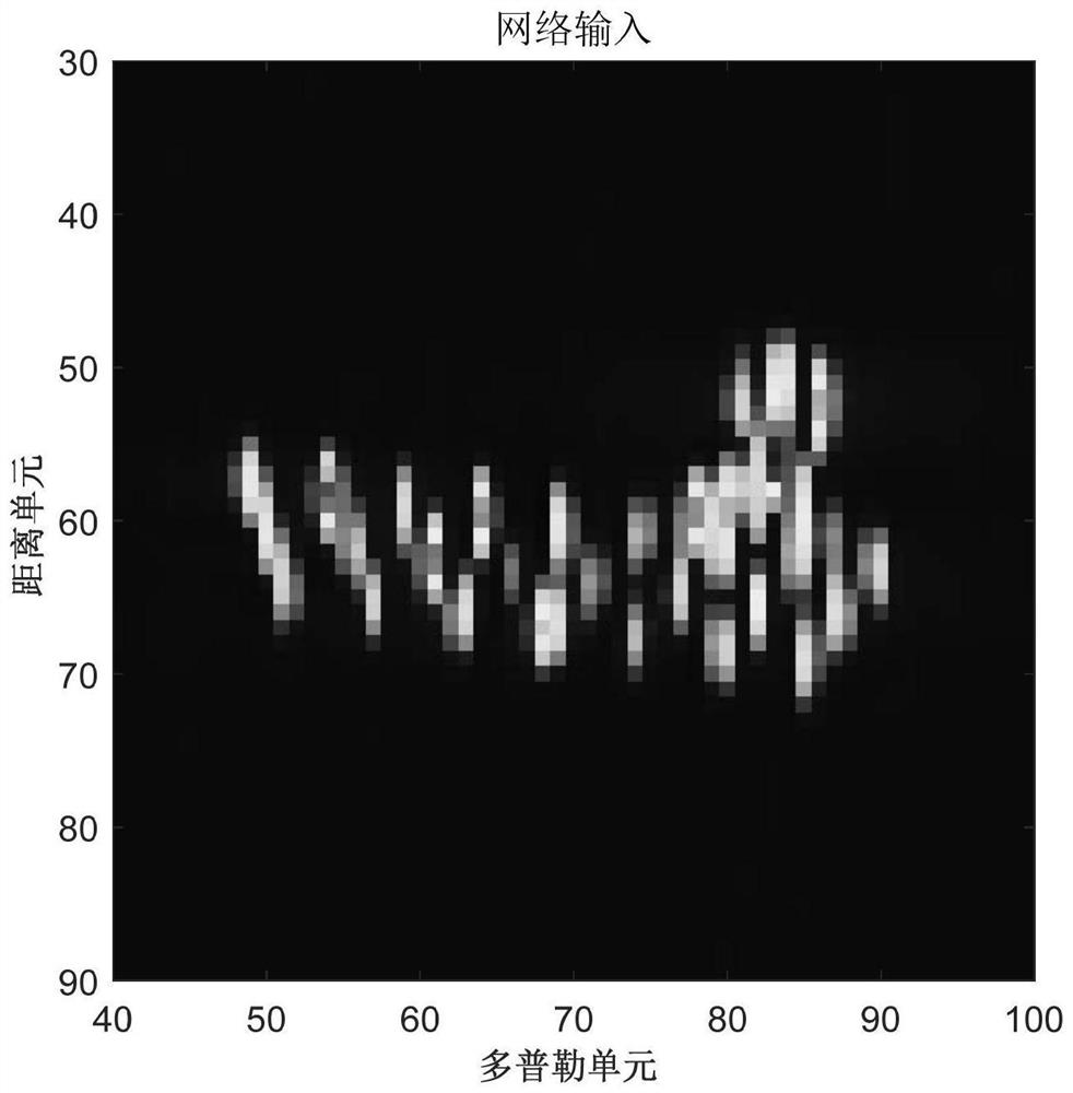
[0061] Specific embodiment two: the difference between this embodiment and specific embodiment one is that the point coordinates (P(x i ,y i )) and motion parameters (angular velocity ω and angular acceleration γ) to calculate the Doppler frequency of the scattering point, thereby determining the distance unit and Doppler unit where the scattering point is imaged at the moment, and obtaining the reference image of the target; the specific process is:
[0062] Step 31. Assume that the carrier frequency is f c , the radar with modulation frequency k transmits linear frequency modulation signal s(t)(LFM);
[0063]
[0064] Where t is the fast time, τ is the pulse width, j is the imaginary unit, j 2 =-1;
[0065] For the instantaneous distance from the radar as R(t m ) target, the echo s(t,t) received by the radar m )Expressed as
[0066]
[0067] where t m is the slow time, σ i Indicates the echo amplitude of the i-th scattering point; R i (t m ) represents the i-...
specific Embodiment approach 3
[0079] Specific embodiment three: the difference between this embodiment and specific embodiment one or two is that in the step five, the ResU-Net network (using the residual block to improve the traditional U-Net network structure to obtain ResU-Net) includes an input layer, Coding unit, connection unit, decoding unit and output layer;
[0080] The coding unit sequentially includes a first coding subunit, a first maximum pooling layer, a second coding subunit, a second maximum pooling layer, a third coding subunit, a third maximum pooling layer, and a fourth coding subunit , the fourth maximum pooling layer;
[0081] The first encoding subunit sequentially includes a first convolutional layer, a first Relu activation layer, and a first residual block;
[0082] The second encoding subunit sequentially includes a second convolutional layer, a second Relu activation layer, and a second residual block;
[0083] The third encoding subunit sequentially includes a third convolutio...
PUM
 Abstract
Description
Claims
Application Information
 - R&D
- Intellectual Property
- Life Sciences
- Materials
- Tech Scout
- Unparalleled Data Quality
- Higher Quality Content
- 60% Fewer Hallucinations
Browse by: Latest US Patents, China's latest patents, Technical Efficacy Thesaurus, Application Domain, Technology Topic, Popular Technical Reports.
© 2025 PatSnap. All rights reserved.Legal|Privacy policy|Modern Slavery Act Transparency Statement|Sitemap|About US| Contact US: help@patsnap.com


