
Electromagnetic speed reduction motor with electromagnetic protection structure and use method of electromagnetic speed reduction motor

A technology of protection structure and electromagnetic deceleration, which is applied in the field of motors, can solve the problems of inconvenient device output speed, inability to judge whether the speed is fast or slow, and the influence of production equipment, so as to achieve the effect of convenient disassembly and assembly of test sensors and avoiding the continuous transmission of power

Active Publication Date: 2022-03-01
JIAXING UNIV
View PDF9 Cites 1 Cited by
  • Summary
  • Abstract
  • Description
  • Claims
  • Application Information

AI Technical Summary

Problems solved by technology

The deceleration motor is small in size, large in carrying capacity, and stable in operation. The lack of a speed measuring device inside the device makes it inconvenient for users to understand the output speed of the device, and it is impossible to judge whether the speed is fast or slow. When the speed is too fast, it will damage the production equipment. make an impact

Method used


Image

  • Electromagnetic speed reduction motor with electromagnetic protection structure and use method of electromagnetic speed reduction motor
  • Electromagnetic speed reduction motor with electromagnetic protection structure and use method of electromagnetic speed reduction motor
  • Electromagnetic speed reduction motor with electromagnetic protection structure and use method of electromagnetic speed reduction motor

Examples


Embodiment Construction

[0034] The following will clearly and completely describe the technical solutions in the embodiments of the present invention with reference to the accompanying drawings in the embodiments of the present invention. Obviously, the described embodiments are only some, not all, embodiments of the present invention. Based on the embodiments of the present invention, all other embodiments obtained by persons of ordinary skill in the art without making creative efforts belong to the protection scope of the present invention.

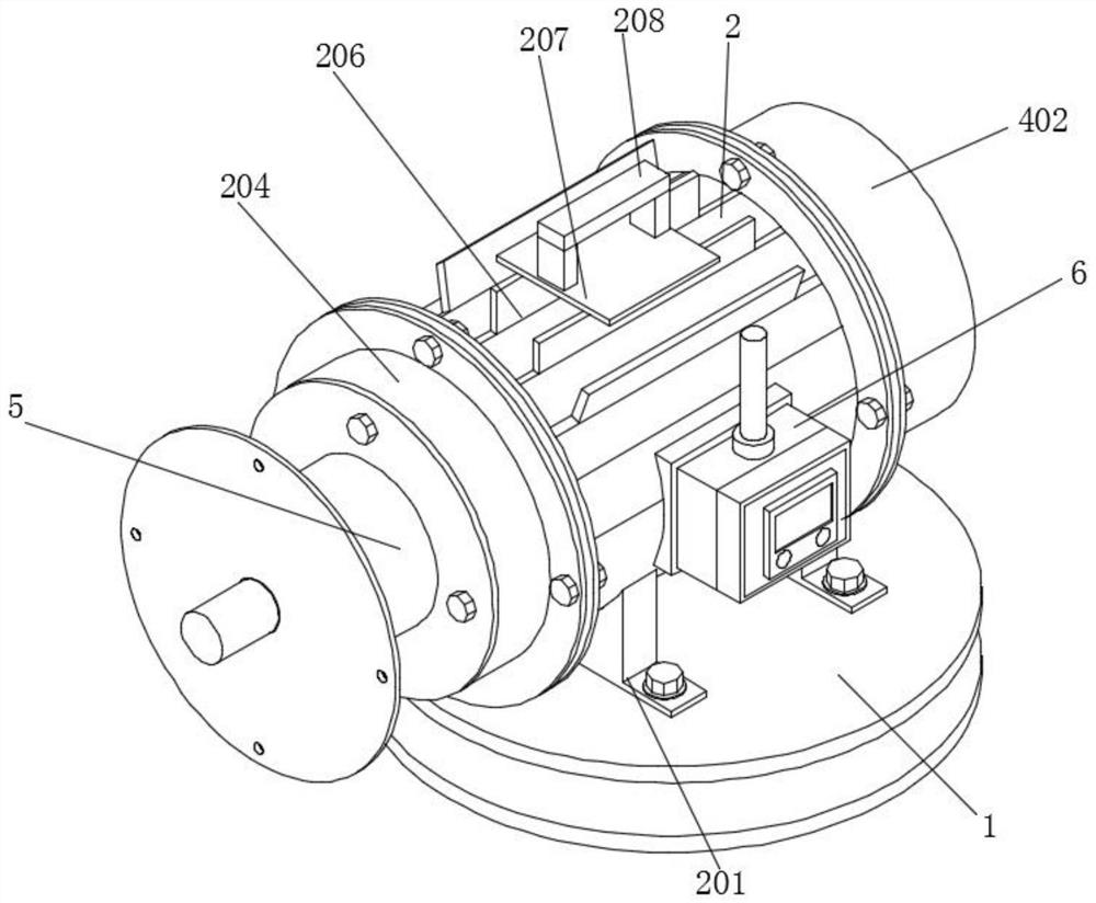
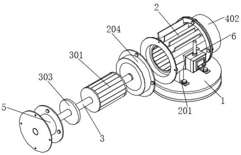
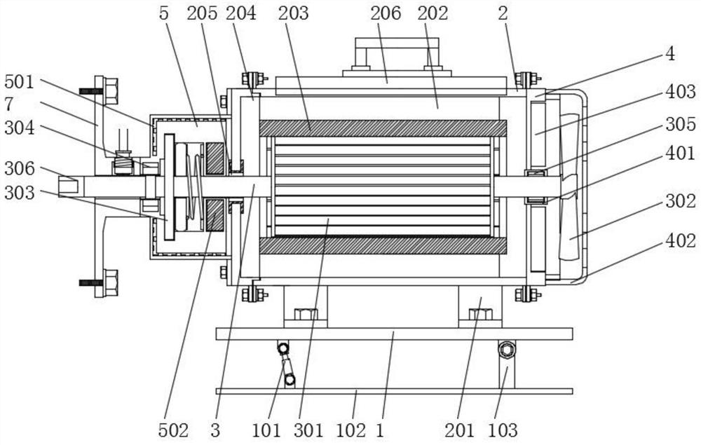
[0035] see Figure 1-Figure 8 , an embodiment provided by the present invention: an electromagnetic geared motor with an electromagnetic protection structure and its use method, including a support platform 1, the top of the support platform 1 is equipped with a support seat 201 through bolts, and the support platform 1 Fix the top support seat 201 to ensure the stability of the support seat 201, and facilitate the support seat 201 to support the top casing 2....


PUM


Abstract

The invention discloses an electromagnetic gear motor with an electromagnetic protection structure and a use method thereof, and the electromagnetic gear motor comprises a supporting table, the top of the supporting table is provided with a supporting seat through a bolt, the top of the supporting seat is provided with a housing, the rear end of the housing is provided with a rear sealing cover through a bolt, and the front end of the housing is provided with a front sealing cover. A supporting bearing is installed on the inner side of the front sealing cover, a supporting ring is installed on the inner side of the rear sealing cover, a limiting bearing is installed on the inner side of the supporting ring, a rotating rod is installed on the inner side of the limiting bearing, and the rotating rod is installed on the inner side of the supporting bearing. By installing the weak magnetic relay, weak magnetic protection of the motor can be achieved by connecting the weak magnetic relay into a motor magnetic loop, in the starting and running process of the motor, when the weak magnetic current value reaches the action value of the weak magnetic relay, the relay is attracted, the normally open contact connected in series in the control circuit is closed, and the motor is started. And the motor is allowed to maintain normal operation.

Description

technical field [0001] The invention relates to the technical field of motors, in particular to an electromagnetic geared motor with an electromagnetic protection structure and a method for using the same. Background technique [0002] The motor converts electrical energy into mechanical energy and provides power for the device. It uses the energized coil to generate a rotating magnetic field and acts on the rotor to form a magnetoelectric force rotating torque, which drives the internal movable parts to rotate for transmission, which can reduce the load on the motor. The dependence on manpower has accelerated the speed of production, and the appearance of electric motors has accelerated the speed of mechanized production, which has provided great help for the progress of society. [0003] The defective that existing electromagnetic reduction motor exists is: [0004] 1. The comparative document CN212935709U discloses a capacitor running gear reduction motor, "including a b...

Claims


Application Information

Patent Timeline
Patent Type & Authority Applications(China)
IPC IPC(8): H02K11/20H02K11/225H02H7/08H02H7/09
CPCH02K11/20H02K11/225H02H7/08H02H7/09H02H7/0854
Inventor 胡劼李传宝赵浩
Owner JIAXING UNIV
Learn More