Preparation method of permanent magnet synchronous motor rotor

A permanent magnet synchronous motor and rotor technology, which is used in the manufacture of motor generators, stator/rotor bodies, electrical components, etc., can solve the problems of motor iron loss, rotor temperature rise, and slot bar bending, etc., to improve quality. and service life, improve guiding reliability, and avoid the effect of circumferential rotation

Pending Publication Date: 2022-03-01
CSR ZHUZHOU ELECTRIC CO LTD
View PDF9 Cites 1 Cited by
  • Summary
  • Abstract
  • Description
  • Claims
  • Application Information

AI Technical Summary

Problems solved by technology

[0002] The structural difference between the permanent magnet synchronous motor and the asynchronous motor is that the interior of the rotor core is fully enclosed. Since the two ends of the magnetic steel groove of the punched sheet are closed after assembly, the rotor core is first stacked with punched sheets, and then the core is pressed by a hydraulic press. The height is compressed to a specific size, so in the process of stacking the punches, the length of the groove-like rods placed in the punching magnetic steel grooves for positioning will inevitably be limited. If the length of the groove-like rods is greater than that after compression The specific size of the rotor core will cause the slot-like rod to bend when the rotor core is pressed, and the phenomenon that the magnetic steel slot of the rotor core will be deformed
If the length of the slot-like rod is shorter than the specific size of the iron core after compaction, then the rotor punching near the D end is prone to loose pieces and dislocation quality problems
Scattering leads to motor iron loss and no-load current increase, rotor punching misalignment leads to vent interference, rotor temperature rise increases, and has a greater impact on the magnetism of the magnet

Method used


Image

  • Preparation method of permanent magnet synchronous motor rotor
  • Preparation method of permanent magnet synchronous motor rotor
  • Preparation method of permanent magnet synchronous motor rotor

Examples


Embodiment Construction

[0025] Combine below Figure 1~6 Embodiments of the present invention are described in detail.

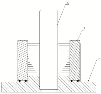
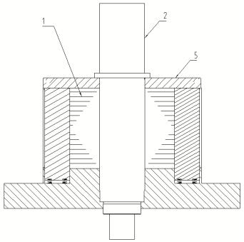
[0026] The preparation method of the rotor of the permanent magnet synchronous motor is to form the iron core 1 by laminating and pressing the punching sheets first, and then install the rotating shaft 2 on the iron core 1 by shrinking the sleeve. The sample rod 3 guides and positions the punching sheet, and the flexible groove sample rod 3 is compressed synchronously with the punching sheet during the pressing process.

[0027] In the method for preparing the rotor of the permanent magnet synchronous motor described above, the flexible groove-like rod 3 is used for guidance and positioning during the stacking process of the punching sheets. pressure, the length of the flexible groove-like rod protruding from the lower die base is greater than the total height of the stacked punches, so that the punches laminated to the top will also form a guiding and positioning cooperation with...


PUM


Abstract

The preparation method of the permanent magnet synchronous motor rotor comprises the following steps of: firstly, laminating and press-fitting punching sheets to form an iron core, and then mounting a rotating shaft on the iron core in a hot jacket manner, and is characterized in that: in the laminating process, the punching sheets are guided and positioned by adopting a telescopic flexible groove-shaped rod, and in the press-fitting process, the flexible groove-shaped rod is synchronously compressed along with the compression of the punching sheets. According to the invention, the quality problems of sheet scattering and dislocation of the top part in the press-fitting process of the punching sheet can be avoided, and the flexible groove-shaped rod is synchronously compressed along with the pressing of the punching sheet in the press-fitting process, so that the circumferential rotation of the punching sheet in the press-fitting process can be effectively avoided; and the flexible groove-shaped rod can be prevented from being pressed and bent to form transverse interference on the punching sheet in the punching sheet press-fitting process, the punching sheet press-fitting process is not interfered by the flexible groove-shaped rod, dislocation and deformation are avoided, it is guaranteed that the ventilation holes of the iron core are not bent in the axial direction, the quality of the iron core is improved, and the service life of the iron core is prolonged.

Description

technical field [0001] The invention relates to a method for preparing a permanent magnet synchronous motor rotor, belonging to the technical field of motor rotor manufacturing. Background technique [0002] The structural difference between the permanent magnet synchronous motor and the asynchronous motor is that the interior of the rotor core is fully enclosed. Since the two ends of the magnetic steel groove of the punched sheet are closed after assembly, the rotor core is first stacked with punched sheets, and then the core is pressed by a hydraulic press. The height is compressed to a specific size, so in the process of stacking the punches, the length of the groove-like rods placed in the punching magnetic steel grooves for positioning will inevitably be limited. If the length of the groove-like rods is greater than that after compression The specific size of the rotor core will cause the slot-like rods to bend when the rotor core is pressed, and deform the magnetic ste...

Claims


Application Information

Patent Timeline
Patent Type & Authority Applications(China)
IPC IPC(8): H02K15/03
CPCH02K15/03
Inventor 熊骞杨学军贺北平徐小涵肖连新杨琰河肖孝轩杨小榆
Owner CSR ZHUZHOU ELECTRIC CO LTD
Why Eureka
Try Eureka