Anti-shake camera module

A technology for camera modules and components, applied in image communication, TV, color TV components and other directions, can solve the problems of poor reliability of the driving device, damage to the camera module, damage, etc., to reduce the accumulation and improvement of tolerances Imaging quality, cost-saving effect

Pending Publication Date: 2022-03-01
NINGBO SUNNY OPOTECH CO LTD
View PDF0 Cites 0 Cited by
  • Summary
  • Abstract
  • Description
  • Claims
  • Application Information

AI Technical Summary

Problems solved by technology

[0004] However, there are still some problems in the existing camera module anti-shake design
For example, in general, in order to achieve better shooting quality, the camera module will increase the volume of its constituent components, and at the same time have higher requirements for the driving device, and the driving device will increase its volume accordingly in order to provide greater driving force , but the above-mentioned volume change does not meet the current requirements for miniaturization of the camera module structure
[0005] In addition, the components of the driving device in the existing anti-shake camera module are relatively complicated. During the assembly process, after the driving device is assembled with other components of the camera module, the reliability of the driving device will deteriorate. If you hit it, it may damage the assembled camera module
For example, when the camera module is not working, the movable part will move relative to the fixed part under the action of external force, which may cause damage or damage to the internal components of the camera module
The internal components of the camera module are all precision components, damage or damage to the above components may lead to a decline in the overall function of the camera module and damage the shooting quality

Method used


Image

  • Anti-shake camera module
  • Anti-shake camera module
  • Anti-shake camera module

Examples


Embodiment Construction

[0072] For a better understanding of the application, various aspects of the application will be described in more detail with reference to the accompanying drawings. It should be understood that these detailed descriptions are descriptions of exemplary embodiments of the application only, and are not intended to limit the scope of the application in any way. Throughout the specification, the same reference numerals refer to the same elements. The expression "and / or" includes any and all combinations of one or more of the associated listed items.

[0073] It should be noted that in this specification, expressions of first, second, third, etc. are only used to distinguish one feature from another, and do not represent any limitation on the features. Thus, a first surface discussed hereinafter could also be termed a second surface without departing from the teachings of the present application. vice versa.

[0074] In the drawings, the thickness, size and shape of components ...


PUM


Abstract

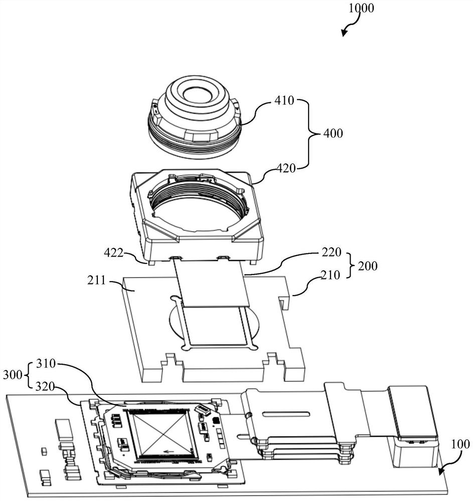
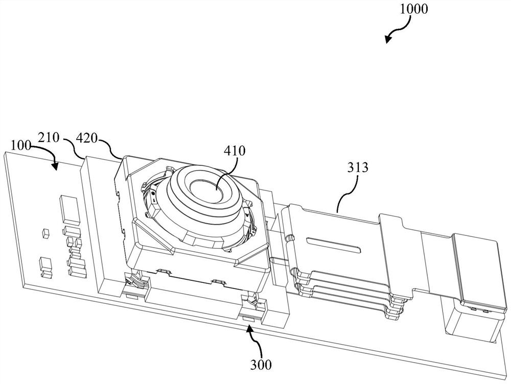
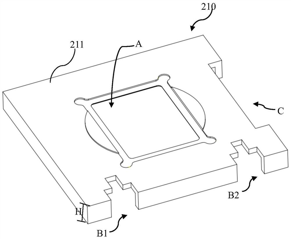
The invention provides an anti-shake camera module. The anti-shake camera module comprises a camera module mainboard, a light filtering assembly and a photosensitive driving assembly. The filter assembly includes a filter support having a predetermined height and a filter disposed on a first surface of the filter support. Wherein the optical filter supporting piece is fixed on the camera module mainboard to form an accommodating space; the photosensitive driving assembly comprises a photosensitive assembly and a driving assembly connected with the photosensitive assembly, and the photosensitive driving assembly is arranged in the accommodating space; and the driving assembly comprises a movable part and a fixed part, and the movable part is connected with the fixed part through the SMA component so as to drive the photosensitive assembly to move in the accommodating space in a conducting state of the SMA component.

Description

technical field [0001] The present application relates to the field of optical imaging technology, and more specifically, to an anti-shake camera module, a preparation method of the anti-shake camera module, a shake correction system, and a terminal device including the anti-shake camera module. Background technique [0002] As the zoom performance of the camera module continues to increase, the requirements for its anti-shake capability also increase accordingly. The anti-shake camera module includes a drive device, which can drive the components of the camera module that are displaced due to shaking to reset. The drive device is usually composed of a movable part and a fixed part. The movable part is fixed together, and when the movable part moves relative to the fixed part, it can drive the components of the camera module fixed together with it to adjust its position. [0003] Among the various existing driving devices, there are many driving methods, for example, the po...

Claims


Application Information

Patent Timeline
Patent Type & Authority Applications(China)
IPC IPC(8): H04N5/232H04N5/225
CPCH04N23/55H04N23/682H04N23/687
Inventor 魏罕钢何艳宁蒋泽娇袁栋立刘旭辉张焕杰刘傅文
Owner NINGBO SUNNY OPOTECH CO LTD
Why Eureka
Try Eureka