Device for carrying out gas-liquid separation by utilizing magnetic screen, working method and spacecraft

A technology of gas-liquid separation and screen, which is applied in the field of space vehicles, can solve the problems of low cost and failure to provide, and achieve the effects of no additional energy consumption, convenient operation, and good air and liquid discharge performance

Active Publication Date: 2022-03-04
SHANGHAI INST OF SPACE PROPULSION
View PDF7 Cites 0 Cited by
  • Summary
  • Abstract
  • Description
  • Claims
  • Application Information

AI Technical Summary

Problems solved by technology

[0015] None of the above-mentioned existing patents can provide a device with low cost, low energy consumption and good gas-liquid separation ability under microgravity

Method used


Image

  • Device for carrying out gas-liquid separation by utilizing magnetic screen, working method and spacecraft
  • Device for carrying out gas-liquid separation by utilizing magnetic screen, working method and spacecraft
  • Device for carrying out gas-liquid separation by utilizing magnetic screen, working method and spacecraft

Examples


Embodiment 1

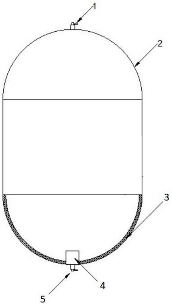
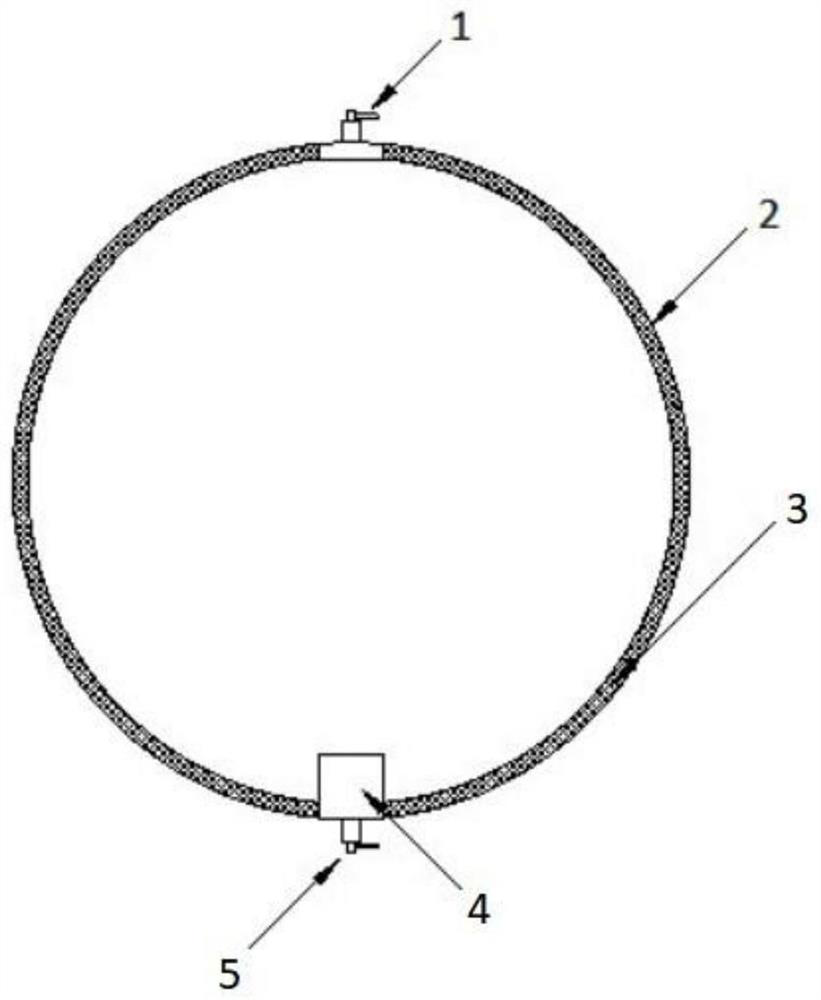
[0051] Such as figure 1 , figure 2 and Figure 4 As shown, a device for gas-liquid separation using a magnetic screen can be used in a space vehicle, including: a housing 2 and a channel 3 with a screen; a channel 3 with a screen and a gas-liquid mixed fluid are installed in the housing 2, and the gas-liquid The mixed fluid includes liquid and gas, and the channel 3 with the screen forms a gradient magnetic field, and the gas-liquid mixed fluid flows to the channel 3 with the screen through the gradient magnetic field, and the liquid without entraining gas is separated through the channel 3 with the screen. An inlet 1 is installed on the top of the housing 2 , an outlet 5 is installed on the bottom of the housing 2 , the outlet 5 is connected to the collector 4 , and the collector 4 is connected to the channel 32 .

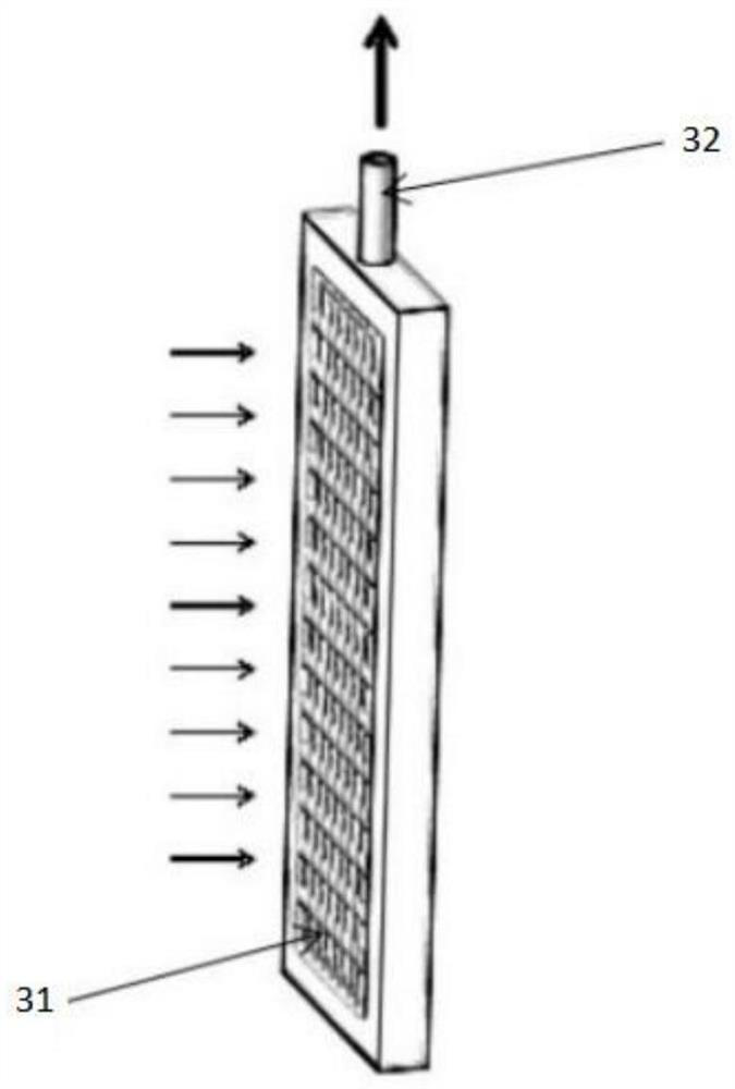
[0052] Such as image 3 As shown, a channel 32 is set inside the channel 3 with a screen, and a screen 31 is installed outside the channel 32. The screen 31 for...

Embodiment 2

[0056] Embodiment 2 is a preferred example of Embodiment 1.

[0057] Such as Figure 1 to Figure 4 As shown, a device for gas-liquid separation using a magnetic screen. The gas-liquid mixed fluid is separated through the screen 31. Under certain conditions, the liquid without gas can pass through the screen 31 smoothly, and the gas cannot break through the surface of the screen 31 to form The liquid film, the screen 31 is made of magnetic material or can generate a stable magnetic field after being magnetized, the magnetic induction intensity of the magnetic field decays from the surface of the screen 31 to both sides away from the screen, thus showing as a gradient magnetic field pointing to the surface of the screen 31 .

[0058] More specifically, if liquid oxygen is a strong paramagnetic fluid, oxygen molecules in a magnetic field will experience a magnetizing force pointing to the direction of increasing magnetic field strength. When the gas-liquid mixed fluid is in the...

Embodiment 3

[0062] Channel 3 with screen can be installed in a semi-management mode or a full-management mode.

[0063] exist figure 1 The channel 3 with a screen mesh adopts a semi-management installation method: the upper end of the shell 2 is the inlet 1, and the lower end is the outlet 5. Channel 3 with screen is installed in the lower half of housing 2 and connected to collector 4 , which is connected to outlet 5 . The gas-liquid mixed fluid enters the lower part of the housing 2 from the inlet 1 and finally fills the channel 3 with a screen. The gas-liquid mixed fluid passes through the channel 3 with a screen for gas-liquid separation, and the liquid without entrainment gathers in the collector 4 and flows from the outlet 5 discharge.

[0064] exist figure 2 The channel 3 with a screen mesh adopts a full-management installation method: the upper end of the shell 2 is the inlet 1, and the lower end is the outlet 5. A channel 3 with a screen is installed on the inner wall of the...


PUM


Abstract

The invention provides a device for carrying out gas-liquid separation by utilizing a magnetic screen, a working method and a spacecraft. The device comprises an inlet, a shell, a channel with a screen and an outlet, one end of the shell is provided with the inlet, and the other end of the shell is provided with the outlet; the channel with the screen is mounted in the shell; the channel with the screen forms a gradient magnetic field, gas-liquid mixed fluid flows into the channel with the screen through the inlet, gas-free liquid is separated out through the gradient magnetic field, and the gas-free liquid is discharged through the outlet. According to the device, magnetizing force is applied to gas-liquid mixing, the gas blocking capacity of a screen liquid film is improved, and therefore better gas-entrapment-free liquid discharging performance is obtained.

Description

technical field [0001] The invention relates to a gas-liquid separation device, in particular to a device, a working method and a space vehicle for gas-liquid separation using a magnetic screen. Background technique [0002] Sieve is one of the main means to achieve gas-liquid separation in the acceleration-free environment under microgravity, and plays an important role in space fluid transmission. In the microgravity environment of space, the gas-liquid fluid is in a floating state, so when the fluid is transported in space, it may entrain the gas and transmit it downstream. In order to realize liquid transmission without entrainment of air, researchers at home and abroad have found that the use of screens and composite devices can achieve liquid discharge without entrainment of air under a certain pressure difference. In this device, the fluid in the spherical container needs to enter four channels placed at 90 degrees through the screen, collect to the collector at the ...

Claims


Application Information

Patent Timeline
Patent Type & Authority Applications(China)
IPC IPC(8): B01D47/02
CPCB01D47/028B01D50/00
Inventor 张瑞平齐宝恒朱文杰周正潮王婷婷邱中华
Owner SHANGHAI INST OF SPACE PROPULSION
Why Eureka
Try Eureka