Casting type guide arm for air suspension
An air suspension and guide arm technology, which is applied to suspensions, elastic suspensions, cantilevers mounted on pivots, etc., can solve problems such as poor coordination and bulky body, and achieve weight reduction, uniform force, Ensure the effect of coordination
- Summary
- Abstract
- Description
- Claims
- Application Information
AI Technical Summary
Problems solved by technology
Method used
Image

Examples
Embodiment Construction
[0019] In order to make the purpose, technical solutions and advantages of the embodiments of the present invention clearer, the technical solutions in the embodiments of the present invention will be clearly and completely described below in conjunction with the drawings in the embodiments of the present invention. Obviously, the described embodiments It is a part of embodiments of the present invention, but not all embodiments. Based on the embodiments of the present invention, all other embodiments obtained by persons of ordinary skill in the art without making creative efforts belong to the protection scope of the present invention.
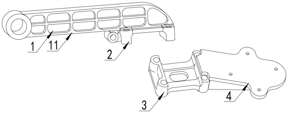
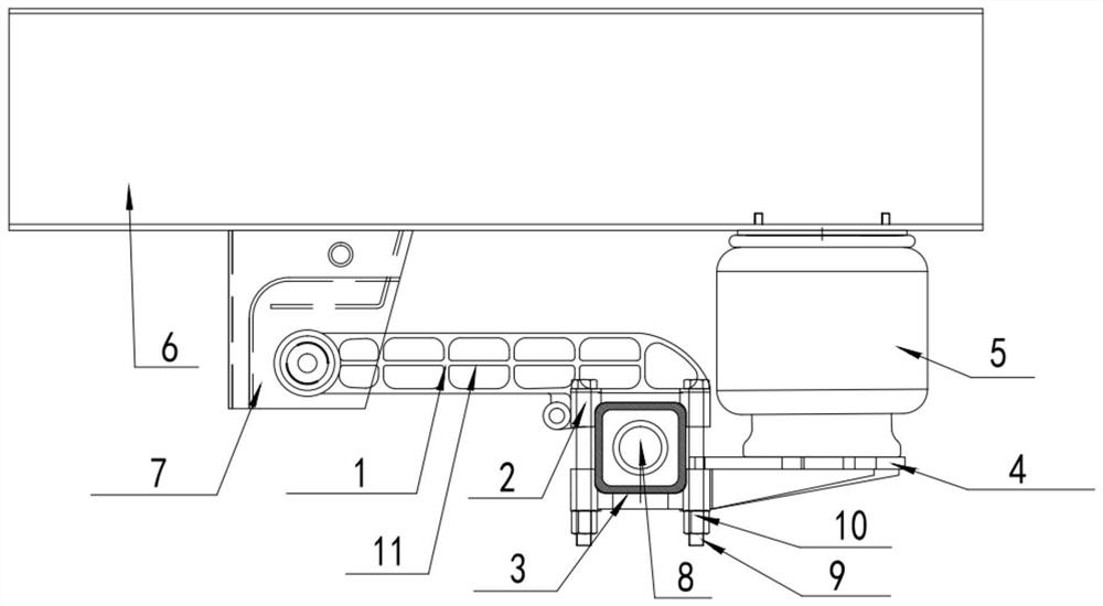
[0020] Reference attached Figure 1-2 , the invention discloses a casting type guide arm for air suspension, comprising: a guide arm body 1, an upper supporting plate 2, a lower supporting plate 3 and an airbag mounting support 4, the upper supporting plate 2 is located at the bottom of the guiding arm body 1 , and cast as one with the guide...
PUM
 Abstract
Description
Claims
Application Information