
Longitudinal connecting plate type ballastless track temperature force release device and method

A technology of slab-type ballastless track and release device, applied in the field of rail transit, can solve the problems that cannot be used to eliminate the risk of temperature deformation and instability of ballastless track, stress concentration of planting reinforcement holes, and degradation of anchoring effect, and achieves simple construction and little disturbance. , Good vertical displacement effect

Pending Publication Date: 2022-03-04
SHIJIAZHUANG TIEDAO UNIV
View PDF0 Cites 0 Cited by
  • Summary
  • Abstract
  • Description
  • Claims
  • Application Information

AI Technical Summary

Problems solved by technology

This solution can reduce temperature deformation-related diseases to a certain extent, but there are still various disadvantages, such as stress concentration at the hole of the planting bar, and aging of the planting bar glue, which leads to the degradation of the anchoring effect, etc.
Therefore, planting reinforcement anchorage can be used as a short-term emergency measure, but it cannot be used as the final solution to eliminate the risk of temperature deformation and instability of ballastless track

Method used


Image

  • Longitudinal connecting plate type ballastless track temperature force release device and method
  • Longitudinal connecting plate type ballastless track temperature force release device and method
  • Longitudinal connecting plate type ballastless track temperature force release device and method

Examples


Embodiment Construction

[0038] In order to further understand the content, characteristics, and efficacy of the present invention, it is taken from the following examples and will be described in detail with reference to the following:

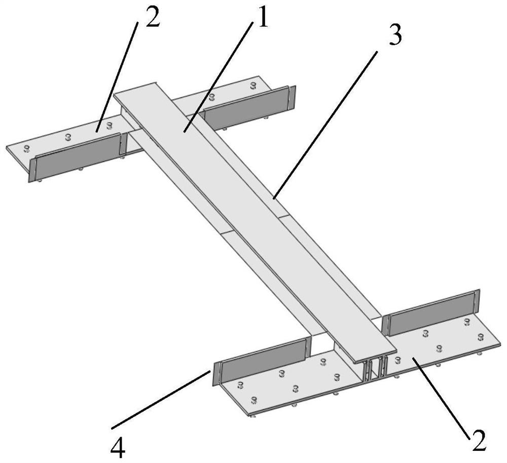
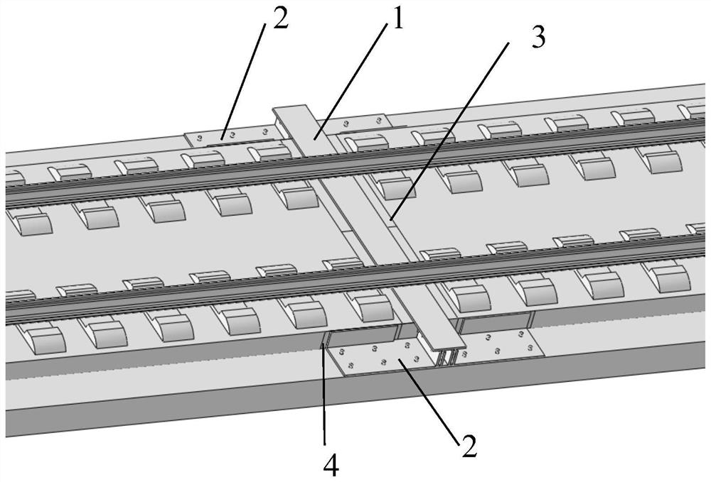
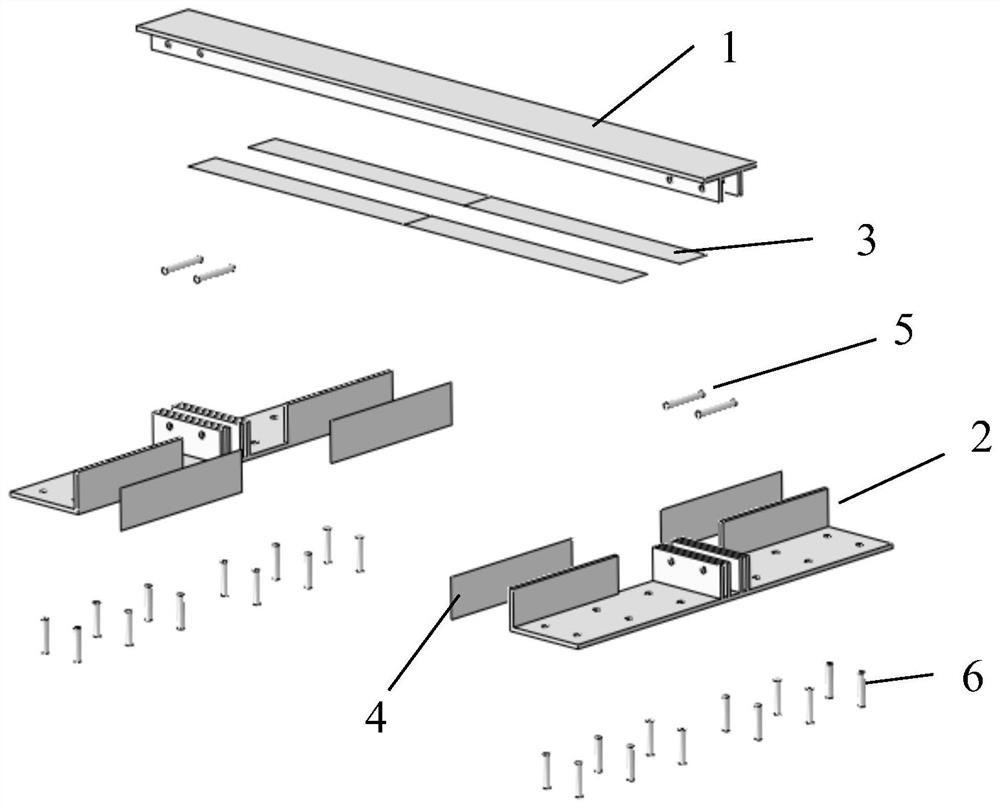
[0039] See Figures 1 to 10 A longitudinal plate-free orbital temperature relief device, including: a radiographic steel beam 1 between the two unit rail plates, a lateral limit frame 2 provided on both sides of the π-type steel beam 1 The side steel sheet 4 is fixed to the left and right side of the front and rear end of the unit rail plate, and the top surface of the top surface of the front and rear end of the unit rail plate is fixed to the top surface of the top and rear ends of the unit track; the π-type steel beam 1 includes parallel to the top of the unit orbord plate. The top plate 1-1 of the surface and two webs 1-2 perpendicular to the top plate 1-1; the lateral limit frame 2 includes a L-bend plate, the L-bending plate including a bottom plate 2-1 and lateral ...


PUM


Abstract

The invention discloses a longitudinal connecting plate type ballastless track temperature force release device which comprises a pi-shaped steel beam located between a front unit track plate and a rear unit track plate, lateral limiting frames symmetrically arranged on the left side and the right side of the pi-shaped steel beam, and side face steel sheets and top face steel sheets fixedly connected to the side faces and the top faces of the front ends and the rear ends of the unit track plates correspondingly. The pi-shaped steel beam comprises a top plate parallel to the top surface of the unit track plate and two webs perpendicular to the top plate; the lateral limiting frame comprises an L-shaped bent plate, the L-shaped bent plate comprises a bottom plate and lateral baffles, the bottom plate is fixedly connected with the track base in parallel, and the lateral baffles are parallel to the left side face and the right side face of the front end and the rear end of the unit track plate. Openings are formed in the centers of the lateral baffles, webs of the pi-shaped steel beams are inserted into the openings, and inserting grooves for inserting the webs are formed in the bottom plate; two side surfaces of the slot are fixedly connected with the web plate; and a top plate of the pi-shaped steel beam is parallel and opposite to the top surface steel sheet. The invention further discloses a temperature force releasing method for the longitudinal connecting plate type ballastless track. According to the invention, transverse and vertical limiting effects are provided for the unit track plate.

Description

Technical field [0001] The present invention relates to a railway technology, and Background technique [0002] At present, the plate-type non-targeted track has the advantages of high laving accuracy, good lines, and widely used in high-speed railways. From the longitudinal connection type, the plate-type non-trail is divided into two types of longitudinal unit and longitudinal continuous (vertical) formula. Longitudinal plate-free tracks have better integration, but because their longitudinal displacement is constrained, when there is a large difference between the actual temperature of the non-trailer, there is a larger longitudinal temperature force, so that The weak links of the track structure, such as a wide narrow seam, a large temperature deformation, thereby causing the arches such as the plate end. Under extremely high temperature conditions in summer, there is a risk of vertical instability, which is seriously dangerous. [0003] In order to prevent temperature deform...

Claims


Application Information

Patent Timeline
Patent Type & Authority Applications(China)
IPC IPC(8): E01B1/00E01B2/00E01B19/00
CPCE01B1/002E01B2/00E01B19/00
Inventor 李杨陈进杰王建西黄守刚陈龙王瑞蔡嘉升
Owner SHIJIAZHUANG TIEDAO UNIV
Learn More