Eureka AIR delivers breakthrough ideas for toughest innovation challenges, trusted by R&D personnel around the world.

Construction device and construction method of steel beam connected platform

A construction device and connection technology, which is applied in the processing of building materials, construction, building construction, etc., can solve the problems of high construction cost, long construction period, slow construction speed, etc., so as to reduce construction labor intensity and construction cost , the effect of fast construction speed

Active Publication Date: 2016-03-02
ZHEJIANG ERJIAN STEEL STRUCTURE
View PDF5 Cites 0 Cited by
  • Summary
  • Abstract
  • Description
  • Claims
  • Application Information

AI Technical Summary

Problems solved by technology

The construction device and construction method of the prior art have the following defects: the one-time input of steel pipes and fastener materials of the full hall scaffolding is large, the consumption is large, and the construction cost is high; It takes a long time and the construction period is long; moreover, the support is dense and occupies all the space under the steel beam connection platform, making the space below unusable for a long time; what's more, the support is high and easy to lose stability, posing a great safety hazard
From the above analysis, it can be known that the erection of scaffolding for welding construction requires many steel pipes and fasteners, a large workload, and time-consuming and laborious installation and disassembly. Moreover, the most important thing is that the operation is suspended at high altitude. The actual operation is extremely difficult and the construction speed is slow. , low efficiency and great security risks

Method used


Image

  • Construction device and construction method of steel beam connected platform
  • Construction device and construction method of steel beam connected platform
  • Construction device and construction method of steel beam connected platform

Examples


Embodiment Construction

[0041] The present invention will be further described below in conjunction with the drawings and specific embodiments.

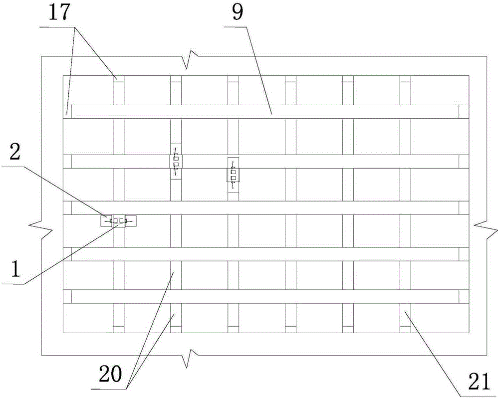
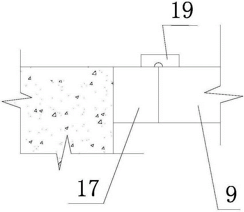
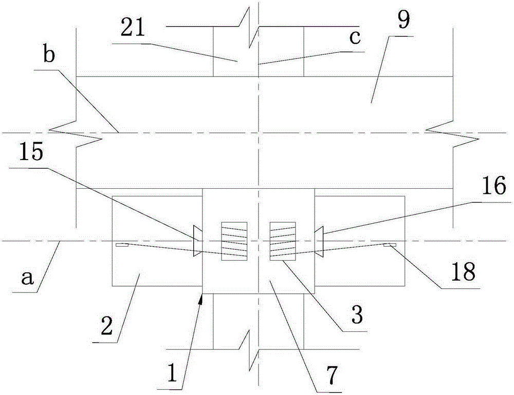
[0042] Such as figure 1 , figure 2 , image 3 , Figure 4 , Figure 5 , Image 6 , Figure 7 , Picture 8 , Picture 9 As shown, the construction device of the steel beam connected platform of the present invention includes a trolley 1 and two operating car baskets 2 located on both sides of the trolley 1. The trolley 1 includes a chassis 6 with rollers 5 and a rotating part 7. The lower end of the rotating part 7 is fixed with a rotating shaft 8, a transmission gear 10 is fixed on the rotating shaft 8, and the rotating part 7 is rotatably fitted on the chassis 6 via the rotating shaft 8. There is a motor 11, and the output gear 12 of the output shaft of the motor 11 meshes with the transmission gear 10. The two operating car baskets 2 are vertically slidingly fitted with the two sides of the rotating part 7 of the trolley 1, that is, the two sides of the ro...


PUM


Abstract

The invention discloses a construction device and a construction method for a steel beam connection platform. The construction device comprises a trolley (1) and two operation car baskets (2), wherein the trolley (1) comprises a chassis and a rotary part (7), a transmission gear is fixedly arranged on the lower end of the rotary part (7), and a motor output gear of the chassis is meshed with the transmission gear; the top of the rotary part (7) and the tops of the operation car baskets (2) are fixed through a winch (3); an electromagnet is arranged on the chassis of the trolley (1); the method comprises the key points that at the normal section position of a main beam (9) or a secondary beam unit (21), the trolley (1) and two operation car baskets (2) move in a manner of clamping the main beam (9) or the secondary beam unit (21) in the triangular structure, when the trolley (1) reaches each node and then lifts the operation car basket (2) through the winch (3), so that the operation car baskets (2) are enabled to be flush with the bottom surface of the trolley (1), so as to pass the node. With the construction device and the construction method, the material consumption is saved, the working intensity is reduced, and the operation is convenient and quick.

Description

Technical field [0001] The invention relates to a construction technology of a steel beam connection type platform in the field of civil engineering, in particular to a construction device and a construction method of a steel beam connection type platform. Background technique [0002] Large-span (generally a span of more than 30m) steel beam frame connected platform includes a platform frame formed by connecting and fixing multiple parallel main beams and multiple parallel and perpendicular secondary beams, main beam and secondary beam The top surface is flush; each main beam is a complete steel beam, and its two ends are respectively fixed on the surrounding concrete structure that has been poured. Specifically, the surrounding concrete structure refers to the poured concrete side walls and columns. Or floor slab, pre-embedded steel corbels on the surrounding concrete structure, the two ends of the main beam are welded and fixed with two steel corbels respectively; each seconda...

Claims


Application Information

Patent Timeline
Patent Type & Authority Patents(China)
IPC IPC(8): E04G21/16
Inventor 张国松
Owner ZHEJIANG ERJIAN STEEL STRUCTURE
Why Eureka
Eureka Blog
Learn More