Small blast hole dumping equipment for mining blasting
A blasting hole, small technology, applied in drilling equipment and methods, drilling equipment, earthwork drilling, etc., can solve the problems of low mining efficiency, increase people's labor intensity, etc., and achieve the effect of improving work efficiency
- Summary
- Abstract
- Description
- Claims
- Application Information
AI Technical Summary
Problems solved by technology
Method used
Image

Examples
Embodiment 1
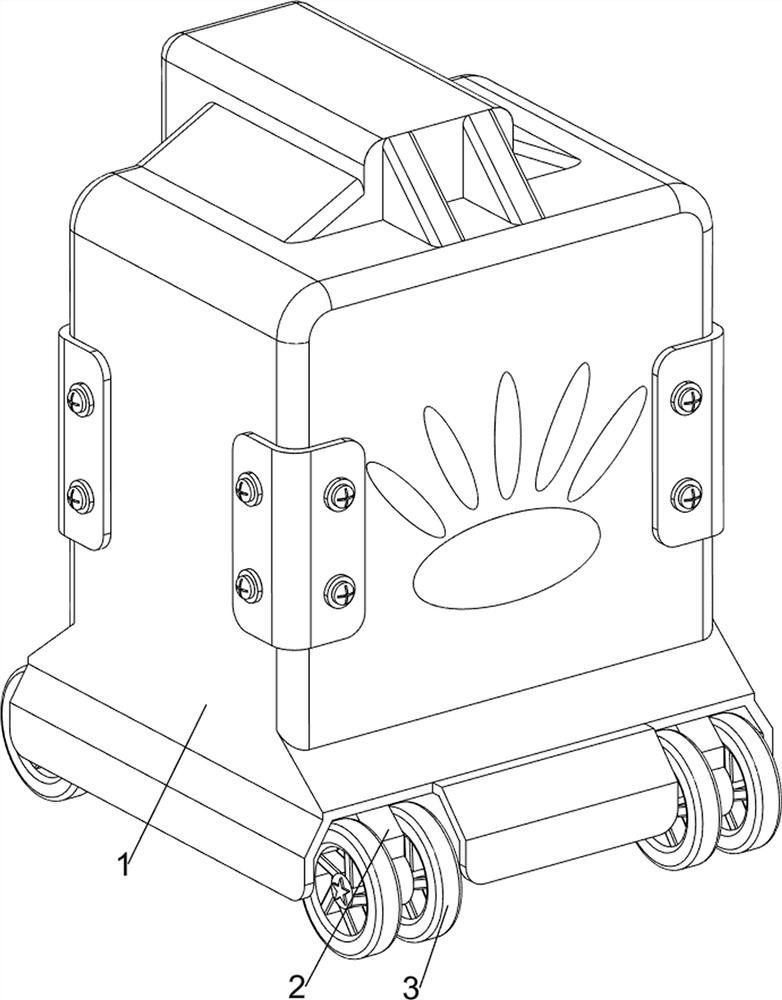
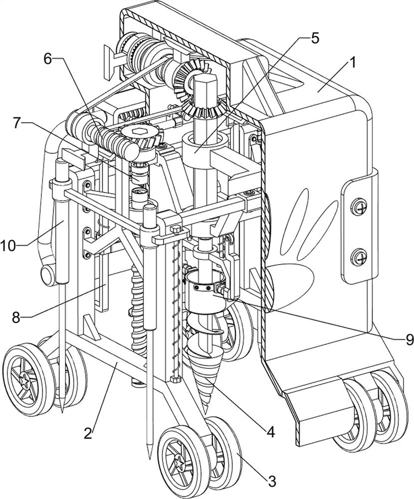
[0032] A kind of small-scale blasting hole excavation equipment for mining blasting, such as Figure 1-Figure 9 As shown, it includes a casing 1, a support frame 2, a wheel 3, a drill bit 4, a soil removal assembly 5, a drive assembly 6 and a starting assembly 7. The inside of the casing 1 is provided with a support frame 2 on the front and rear sides, and the left and right sides of the bottom of the support frame 2 The wheels 3 are symmetrically rotated, the middle of the housing 1 is provided with a soil removal assembly 5, the lower side of the soil removal assembly 5 is provided with a drill bit 4, the inner side of the housing 1 is provided with a driving assembly 6, and the driving assembly 6 is connected to the soil removal assembly 5. A starting component 7 is provided on the upper left side inside the housing 1 , and the starting component 7 cooperates with the driving component 6 .
[0033] The soil removal assembly 5 includes a motor 501, a bevel gear 502, a first ...
Embodiment 2
[0038] On the basis of Example 1, such as Figure 10-Figure 12 As shown, a clamping assembly 8 is also included. The clamping assembly 8 includes a stopper 801, a guide block 802, a first slide bar 803 and a fifth spring 804. The bottom of the push rod 708 is symmetrically provided with a stopper 801. A guide block 802 is symmetrically arranged in the middle of the left side of the inside, and a first slide bar 803 is slidably provided on the inner side of the guide block 802. The stoppers 801 are all matched with the first slide bar 803. Both are provided with fifth springs 804 , and the fifth springs 804 are sleeved on the first sliding rod 803 .
[0039] When people move the push rod 708 to the right, the block 801 is driven to move to the right, so that the block 801 is in contact with the first slide bar 803, which drives the first slide bar 803 to move downward, and the fifth spring 804 is stretched. After the block 801 moves to the right and passes the first slide bar ...
PUM
 Abstract
Description
Claims
Application Information
 - R&D
- Intellectual Property
- Life Sciences
- Materials
- Tech Scout
- Unparalleled Data Quality
- Higher Quality Content
- 60% Fewer Hallucinations
Browse by: Latest US Patents, China's latest patents, Technical Efficacy Thesaurus, Application Domain, Technology Topic, Popular Technical Reports.
© 2025 PatSnap. All rights reserved.Legal|Privacy policy|Modern Slavery Act Transparency Statement|Sitemap|About US| Contact US: help@patsnap.com