Toughened glass impact resistance detection equipment for constructional engineering

A technology of tempered glass and testing equipment, applied in the direction of measuring devices, instruments, scientific instruments, etc., can solve problems such as troubles and affect work efficiency, and achieve the effect of improving work efficiency and facilitating work.

Pending Publication Date: 2022-03-04
谢小金
View PDF0 Cites 0 Cited by
  • Summary
  • Abstract
  • Description
  • Claims
  • Application Information

AI Technical Summary

Problems solved by technology

[0004] In order to overcome the shortcomings of manual handling and loading of tempered glass, which affects work efficiency, and the need for people to manually remove qualified tempered glass, which is more troublesome, the techni

Method used


Image

  • Toughened glass impact resistance detection equipment for constructional engineering
  • Toughened glass impact resistance detection equipment for constructional engineering
  • Toughened glass impact resistance detection equipment for constructional engineering

Examples


Example Embodiment

[0078] Example 1

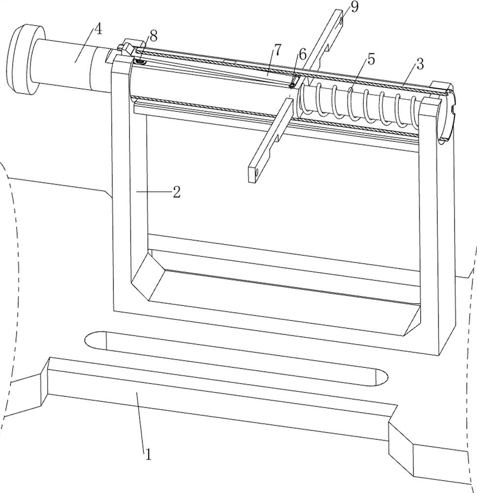
[0079] A kind of tempered glass impact detection equipment for construction engineering, such as Figure 1-Figure 5 As shown, it includes a bottom plate 1, a first support frame 2, a first fixed frame 3, an impact column 4, a striking mechanism, a power mechanism 10, and a fixing mechanism 11. The middle side of the top of the bottom plate 1 is provided with a first support frame 2. The upper part of a support frame 2 is provided with a first fixed frame 3, the first fixed frame 3 is provided with an impact column 4 slidingly, the first fixed frame 3 is provided with a striking mechanism, the top of the bottom plate 1 is provided with a power mechanism 10, and the bottom plate 1 A fixing mechanism 11 is provided on the top.

[0080] The striking mechanism includes a first spring 5, a first fixed block 6, a first block 7, a second spring 8 and a first movable plate 9, and a The first spring 5, the top middle side of the impact column 4 is provided with the ...

Example Embodiment

[0084] Example 2

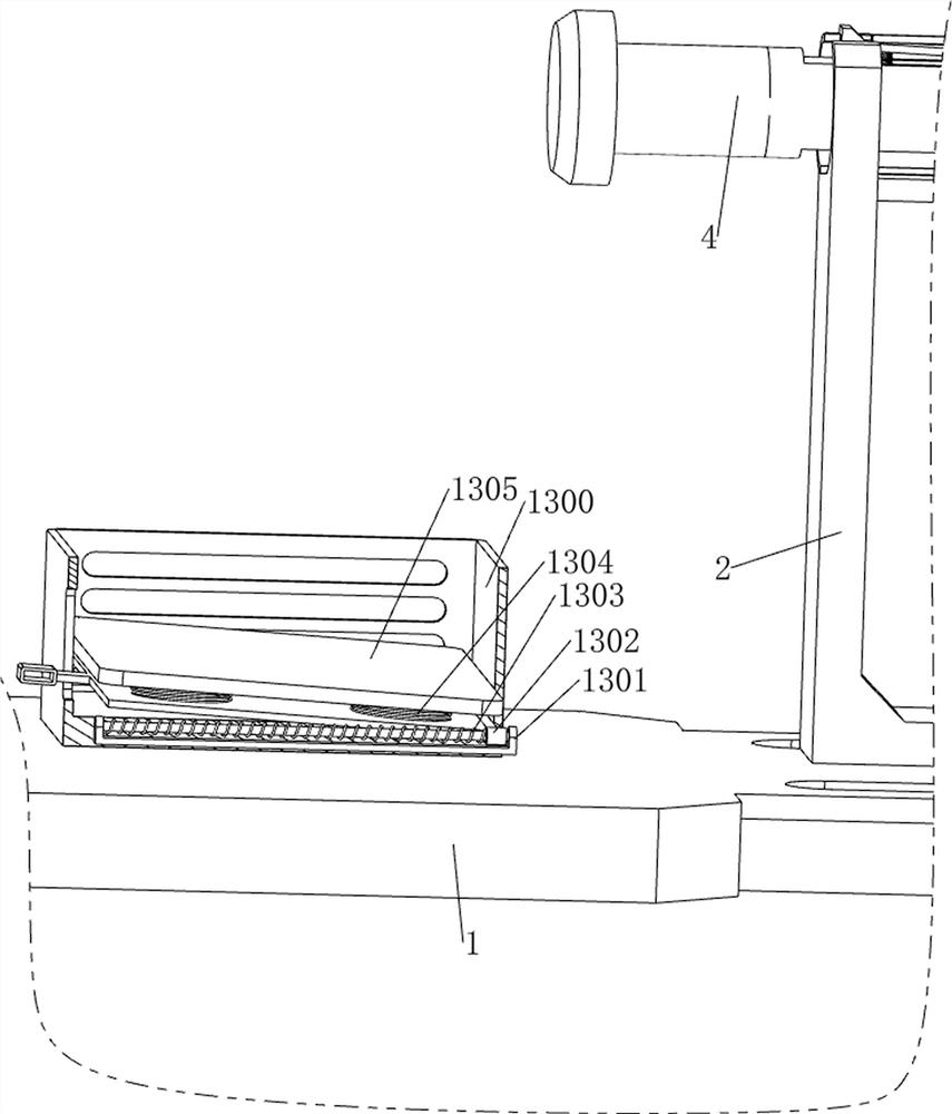
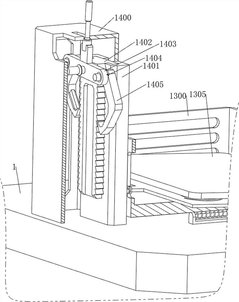
[0085] On the basis of Example 1, such as Figure 6-Figure 8 As shown, a blanking mechanism 12 is also included. The blanking mechanism 12 includes a charging frame 1200, a fourth support frame 1201, a push plate 1202, a handle 1203, a ninth spring 1204, a clamping plate 1205 and a return spring 1206. A charging frame 1200 is arranged between the inner upper part of a fixed plate 1001, a fourth supporting frame 1201 is arranged in the middle part on the right side of the charging frame 1200, and a push plate 1202 is slidingly provided on the right side of the fourth supporting frame 1201, and the right side of the pushing plate 1202 A handle 1203 is provided, a ninth spring 1204 is provided between the front and rear sides of the left part of the push plate 1202 and the inner right side of the fourth support frame 1201, and the lower part of the front and rear sides of the charging frame 1200 is slidingly provided with a clamping plate 1205, The clamping pl...


PUM


Abstract

The invention relates to detection equipment, in particular to tempered glass impact resistance detection equipment for constructional engineering. The tempered glass impact resistance detection equipment for constructional engineering aims at achieving the technical purposes that tempered glass can be automatically and intermittently fed, and qualified tempered glass can be collected. The tempered glass impact resistance detection equipment for constructional engineering comprises a bottom plate and a first supporting frame, and the first supporting frame is arranged on the middle side of the top of the bottom plate; the first fixing frame is arranged at the upper part of the first support frame; the impact column is arranged in the first fixing frame in a sliding manner; the beating mechanism is arranged on the first fixing frame; the power mechanism is arranged at the top of the bottom plate; and the fixing mechanism is arranged at the top of the bottom plate. Through cooperation of the striking mechanism, the power mechanism and the fixing mechanism, tempered glass can be automatically impacted, so that an impact resistance detection experiment is completed, and time and labor are saved.

Description

technical field [0001] The invention relates to a detection device, in particular to a tempered glass impact detection device for construction engineering. Background technique [0002] Tempered glass is glass with compressive stress on the surface, also known as strengthened glass, which is strengthened by tempering method. After tempered glass is produced, it needs to be tested against impact, and only qualified tempered glass can be put into use. [0003] People usually use a heavy object with measured strength to hit the glass, and then the strength of the tempered glass can be detected by calculation. When the number of tempered glass to be detected is large, it is necessary to manually carry the next piece of tempered glass after each detection. Feeding requires a lot of time and effort, which affects work efficiency, and requires people to manually remove the qualified tempered glass, which is more troublesome. Therefore, a device that can automatically intermittentl...

Claims


Application Information

Patent Timeline
IPC IPC(8): G01N3/307G01N3/02
CPCG01N3/307G01N3/02
Inventor 谢小金
Owner 谢小金
Why Eureka
Try Eureka