
Synchronous calibration device and calibration method for trigger signal sending direction

A technology for sending direction and triggering signals, applied in measurement devices, electronic circuit testing, instruments, etc., can solve the problems of AC calibration board digital board difficulty and other problems, and achieve the effect of reducing the difficulty of development

Pending Publication Date: 2022-03-04
SHANGHAI NCATEST TECH CO LTD
View PDF0 Cites 1 Cited by
  • Summary
  • Abstract
  • Description
  • Claims
  • Application Information

AI Technical Summary

Problems solved by technology

[0006] The purpose of the present invention is to provide a test device and a verification method for synchronous calibration of the trigger signal transmission direction, which is used to solve the problem that the AC calibration board is difficult to adapt to different types of digital boards in the prior art

Method used


Image

  • Synchronous calibration device and calibration method for trigger signal sending direction
  • Synchronous calibration device and calibration method for trigger signal sending direction
  • Synchronous calibration device and calibration method for trigger signal sending direction

Examples


Embodiment 1

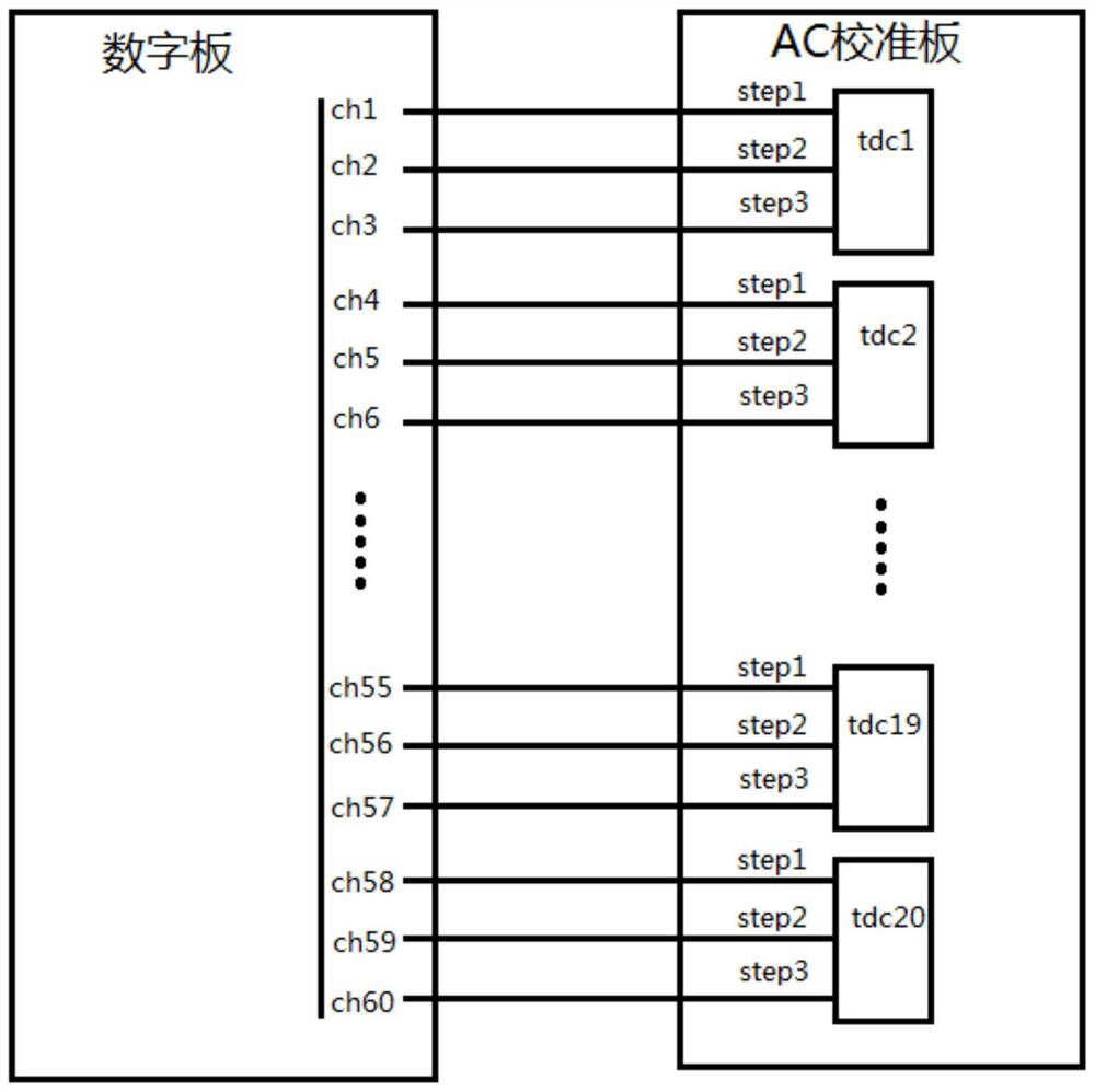
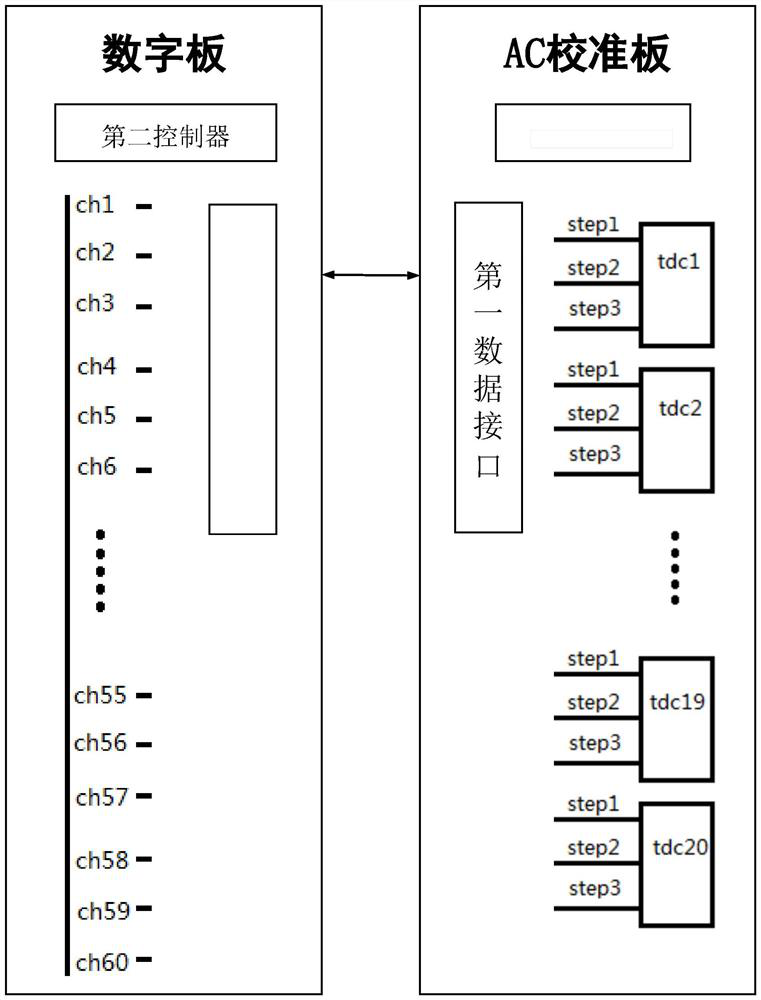
[0030] see figure 2 , figure 2 Shown is a schematic diagram of the connection relationship between each channel of the AC calibration board and the channel of the digital board in the embodiment of the present invention. Such as figure 2 As shown, the synchronous calibration device in the sending direction of the trigger signal includes a digital board module and an AC calibration board module; the AC calibration board includes 20 TDC chips (tdc1, tdc2, ... tdc20), and the digital board includes 60 data channels (ch1, ch2, ... ch60), the connection relationship between each channel of each TDC chip and the channel of the digital board is mainly shown as the mapping relationship between the above channels. Moreover, each TDC chip has three measurement channels (step1, step2 and step3), therefore, 20 TDC chips also have 60 channels.

[0031] In the embodiment of the present invention, the digital board saves the mapping relationship table of its own 60 data channels (ch1, ...


PUM


Abstract

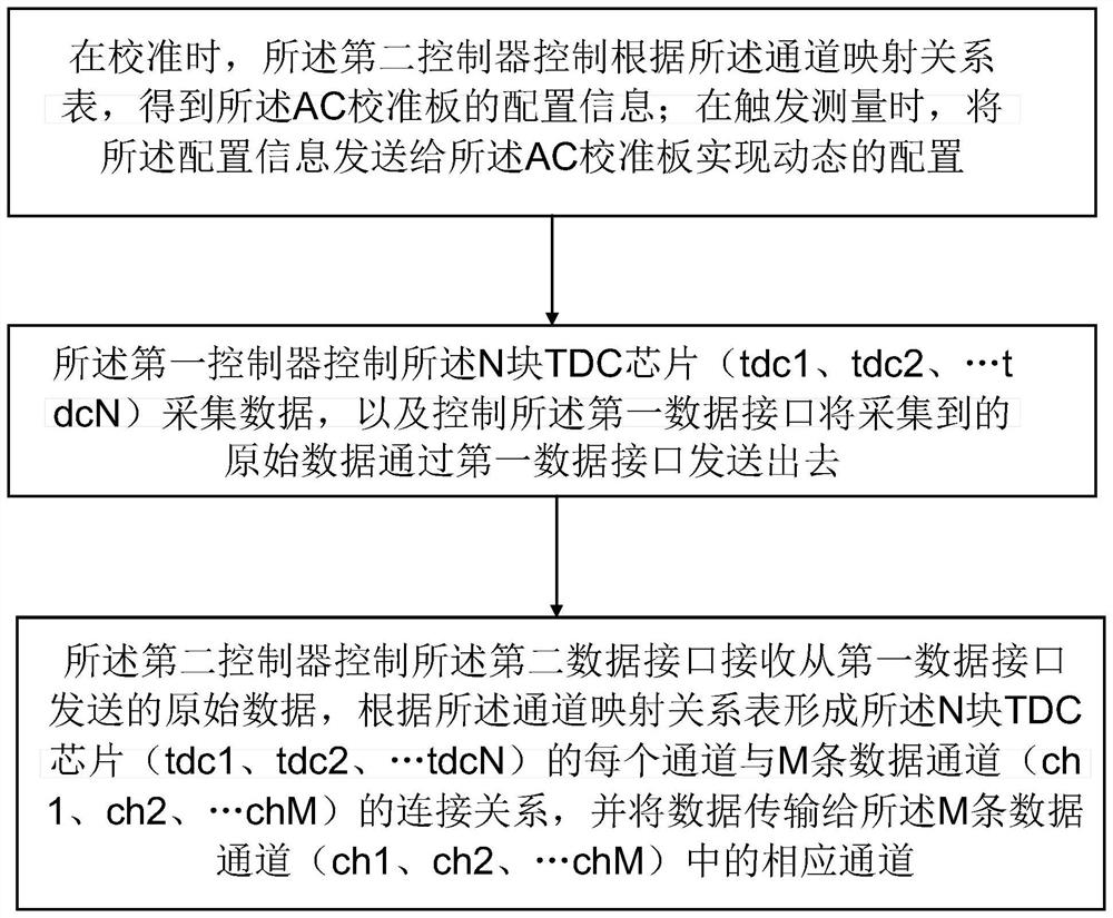
The invention discloses a synchronous calibration device for the sending direction of a trigger signal. The device comprises a digital board module and an AC calibration board module, the AC calibration board module comprises a first data interface, a first controller and N TDC chips (tdc1, tdc2,... tdcN); the first controller controls the N TDC chips (tdc1, tdc2,... tdcN) to collect data, and controls the first data interface to send out collected original data through the first data interface; the digital board module comprises a second data interface, a second controller, a channel mapping relation table and M data channels (ch1, ch2,..., chM); and the second controller controls the second data interface to receive original data sent from the first data interface, forms a connection relationship between each channel of the N TDC chips (tdc1, tdc2,... tdcN) and M data channels (ch1, ch2,... chM) according to a channel mapping relationship table, and obtains and stores delay data in the M data channels (ch1, ch2,... chM).

Description

technical field [0001] The present invention relates to the field of semiconductor automatic test equipment (Automatic Test Equipment, referred to as ATE), in particular to a method and calibration equipment for synchronous calibration of trigger signal sending direction in ATE semiconductor integrated circuit test equipment. Background technique [0002] Adjustment-calibration (Adjustment Caliration, AC) is to determine the value indicated by the measuring instrument or measuring system under specified conditions, or the value represented by the physical measuring tool or reference material, and the corresponding value reproduced by the standard A set of operations on relationships between quantities. The calibration result can not only give the indication value of the measured value, but also determine the correction value of the indication value. [0003] The transmission direction synchronous calibration board (AC calibration board) is a printed circuit board. The AC ca...

Claims


Application Information

Patent Timeline
IPC IPC(8): G01R31/28
CPCG01R31/2882G01R31/2834
Inventor 伍浩东
Owner SHANGHAI NCATEST TECH CO LTD
Learn More