
A visual electronic fence system

Active Publication Date: 2022-04-29
ZHONGSHAN POWER SUPPLY BUREAU OF GUANGDONG POWER GRID
View PDF0 Cites 0 Cited by
  • Summary
  • Abstract
  • Description
  • Claims
  • Application Information

AI Technical Summary

Problems solved by technology

[0004] The invention provides a visual electronic fence system, which is used to solve the technical problem that the existing three-dimensional security electronic fence positioned by laser radar and UWB technology cannot allow on-site operators to intuitively feel the working area and live area, and the reliability is not high.

Method used


Image

  • A visual electronic fence system
  • A visual electronic fence system
  • A visual electronic fence system

Examples


Embodiment Construction

[0041] In order to enable those skilled in the art to better understand the solutions of the present invention, the technical solutions in the embodiments of the present invention will be clearly and completely described below in conjunction with the drawings in the embodiments of the present invention. Obviously, the described embodiments are only It is a part of embodiments of the present invention, but not all embodiments. Based on the embodiments of the present invention, all other embodiments obtained by persons of ordinary skill in the art without making creative efforts belong to the protection scope of the present invention.

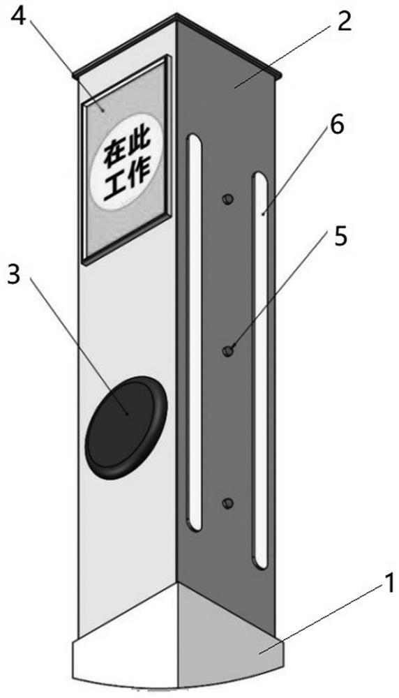
[0042] For ease of understanding, see figure 1 , a visual electronic fence system, including a plurality of electronic fences arranged on the electric power work site;

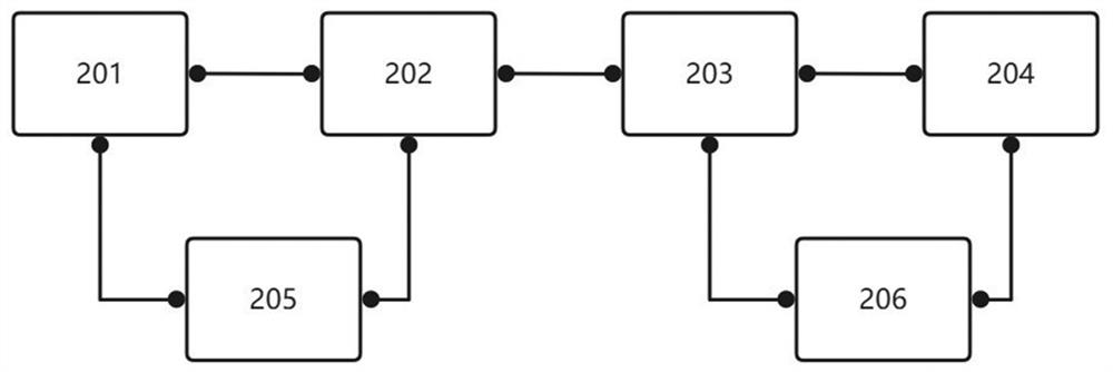
[0043] The electronic railing includes a buried base 1, a lifting column 2, a light emitter 5, an intrusion / break-in sensing component 6, a controller, a voice broadcast device ...


PUM


Abstract

The invention discloses a visual electronic fence system. The electronic fence adopts a buried base, and the lifting column is lowered to the ground when not in use, and the lifting column is raised when in use, and the controller is arranged according to the fence set by the operator The electronic railing corresponding to the information control is raised and lowered, and the optical fiber emission line on the electronic railing emits light to form an optical network, which makes the electronic fence visualized. Personnel give voice prompts, and judge whether there are operators intruding into or out of the operation area through the intrusion / exit sensing component, so as to provide the on-site operators with an intuitive operation area and live area visually and audibly, and solve the problem The existing three-dimensional security electronic fence that uses laser radar and UWB technology positioning cannot allow on-site operators to intuitively feel the operating area and live area, and the technical problems of low reliability.

Description

technical field [0001] The invention relates to the technical field of electronic fences, in particular to a visualized electronic fence system. Background technique [0002] In the electric power operation site, in order to ensure the personal safety of the operators, the operators should keep a necessary safe distance from the nearby high-voltage live equipment. Generally, safety fences are set up to limit the scope of activities of the operators within the specified safety range. [0003] The traditional substation safety fence layout is mainly arranged manually by substation operators using mesh fences, support poles, discus, and signs, which are manually set by substation operators according to the scope of power outages and work needs, and the level of intelligence is low. With the development of power electronics technology, there are three-dimensional security electronic fences that use laser radar and UWB technology to locate. However, with the three-dimensional se...

Claims


Application Information

Patent Timeline
Patent Type & Authority Patents(China)
IPC IPC(8): G08B13/12G08B7/06H04M1/72415H04L67/125G01V8/20
CPCG08B13/122G08B7/06H04M1/72415H04L67/125G01V8/20
Inventor 张永挺李伟谢幸生张勇志汤晓晖严尹廷朱俊超卢锴贺玺睿刘思远肖健文朱兴旺尹国志李衍进张新明
Owner ZHONGSHAN POWER SUPPLY BUREAU OF GUANGDONG POWER GRID
Learn More