
Refrigeration fly-proof camera

A camera and fly-proof technology, applied in the field of cameras, can solve problems such as inconvenience of use and easy accumulation of dust, and achieve the effects of reasonable layout, reduced wind speed attenuation, and compact structure

Inactive Publication Date: 2022-03-04
厦门农芯数字科技有限公司
View PDF0 Cites 0 Cited by
  • Summary
  • Abstract
  • Description
  • Claims
  • Application Information

AI Technical Summary

Problems solved by technology

[0004] The technical problem to be solved by the present invention is to overcome the existing defects and provide a refrigerated anti-fly camera to solve the problem that dust is easy to accumulate on the surface of the camera during the use process proposed in the above background technology, and the dust needs to be cleaned, resulting in inconvenient use question

Method used


Image

  • Refrigeration fly-proof camera
  • Refrigeration fly-proof camera
  • Refrigeration fly-proof camera

Examples


Embodiment 1

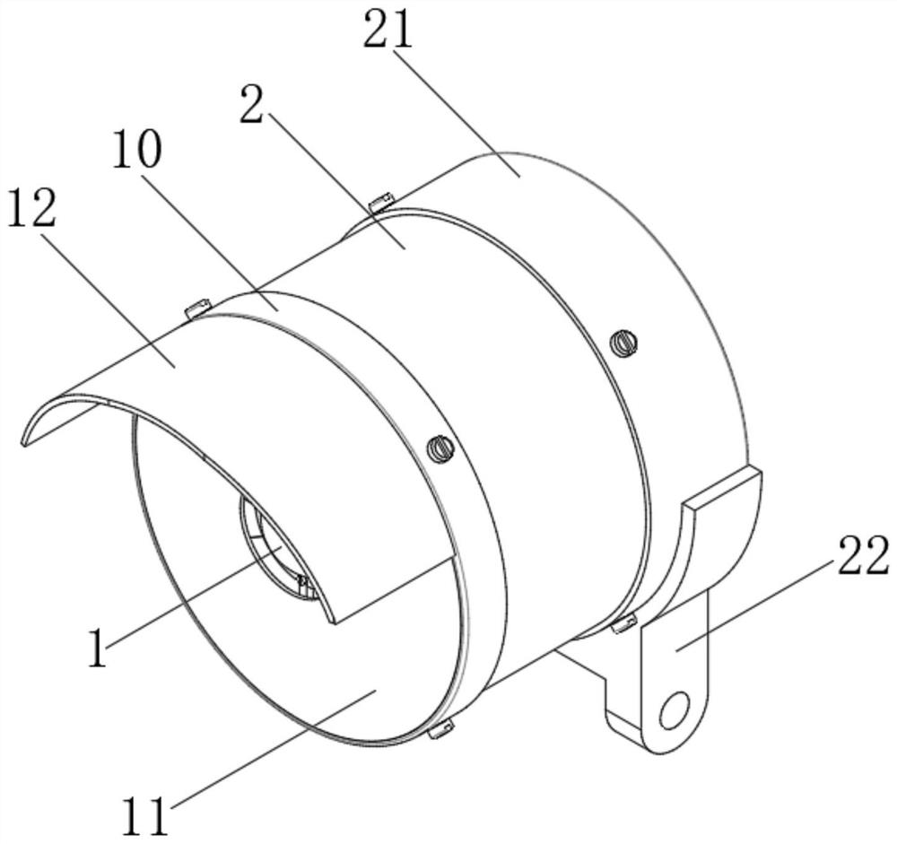
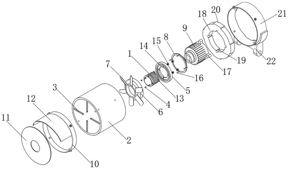
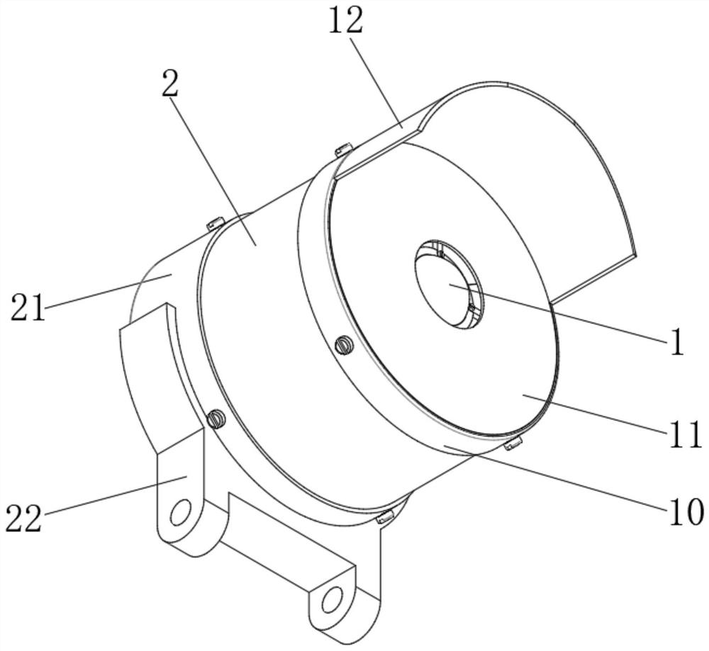
[0032] see Figure 1-8 , the present invention provides a technical solution: a cooling fly-proof camera, including a camera main body 1, the camera main body 1 is located inside the housing 2, and the inner side of one end of the housing 2 is evenly fixed and connected with a connecting frame 3, and the connecting frame 3 is connected by a screw-4 It is fixedly connected with the camera main body 1, and the outer side of the camera main body 1 is rotatably connected with the connecting sleeve 6 through the bearing 5, and the side of the connecting sleeve 6 close to the connecting frame 3 is uniformly provided with fan blades 7, and the other side of the connecting sleeve 6 is fixedly connected by screws 3 16 There is a connection cover 8, the inside of the housing 2 is located on the other side of the connection cover 8, and a drive motor 9 is provided, the output end of the drive motor 9 is engaged with the connection cover 8, and the end of the housing 2 near the connection ...

Embodiment 2

[0037] see Figure 1-8, the present invention provides a technical solution: a cooling fly-proof camera, including a camera main body 1, the camera main body 1 is located inside the housing 2, and the inner side of one end of the housing 2 is evenly fixed and connected with a connecting frame 3, and the connecting frame 3 is connected by a screw-4 It is fixedly connected with the camera main body 1, and the outer side of the camera main body 1 is rotatably connected with the connecting sleeve 6 through the bearing 5, and the side of the connecting sleeve 6 close to the connecting frame 3 is uniformly provided with fan blades 7, and the other side of the connecting sleeve 6 is fixedly connected by screws 3 16 There is a connection cover 8, the inside of the housing 2 is located on the other side of the connection cover 8, and a drive motor 9 is provided, the output end of the drive motor 9 is engaged with the connection cover 8, and the end of the housing 2 near the connection f...


PUM


Abstract

The invention discloses a refrigeration fly-proof camera, which comprises a camera main body, the camera main body is located in a shell, the inner side of one end of the shell is uniformly and fixedly connected with a connecting frame, the connecting frame is fixedly connected with the camera main body through a screw I, and the outer side of the camera main body is rotatably connected with a connecting sleeve through a bearing; the camera body and the driving motor are arranged, the driving end of the driving motor drives the connecting cover to rotate, then the connecting cover drives the connecting sleeve to rotate on the outer side of the camera body through the bearing, the fan blades evenly arranged on the outer side of the connecting sleeve are driven by the driving motor to rotate at a high speed, and then air generated by the fan blades is blown to the air return cover. Under the action of the air return cover, the blown air is guided to one end of the camera main body, so that the surface of the camera main body is always blown by the air, and dust can be prevented from being accumulated on the surface of the camera main body.

Description

technical field [0001] The invention belongs to the technical field of cameras, and in particular relates to a cooling and anti-fly camera. Background technique [0002] Camera, also known as computer camera, computer eye, electronic eye, etc., is a video input device, which is widely used in video conferencing, telemedicine and real-time monitoring; Talk and communicate with voice. In addition, people can also use it for various popular digital images, audio-visual processing and so on. [0003] The existing refrigerated anti-fly camera is easy to accumulate dust on the surface of the camera during use, and the dust needs to be cleaned, resulting in inconvenient use. Therefore, a refrigerated anti-fly camera is proposed. Contents of the invention [0004] The technical problem to be solved by the present invention is to overcome the existing defects and provide a refrigerated anti-fly camera to solve the problem that dust is easy to accumulate on the surface of the came...

Claims


Application Information

Patent Timeline
Patent Type & Authority Applications(China)
IPC IPC(8): H04N5/225B08B5/02
CPCB08B5/02H04N23/50H04N23/51
Inventor 薛素金林灵杰
Owner 厦门农芯数字科技有限公司
Learn More