High-precision curve guide rail powered driving mechanism based on double datum planes and robot

A technology of curved guide rails and datum planes, applied in the directions of manipulators, claw arms, manufacturing tools, etc., can solve the problems of wear of parts and the inability of rail-mounted robots to accurately control the driving distance, and achieve the effect of reducing wear and tear.

Pending Publication Date: 2022-03-08
HANGZHOU SHENHAO TECH
0 Cites 0 Cited by

AI-Extracted Technical Summary

Problems solved by technology

[0003] The embodiment of the present application provides a high-precision curved guide rail electric drive mechanism and its robot based on double reference planes, so as to at least solve the problem that the rail-mounted robot in the ...

Method used

Described electric brush head 5.4 can be set to one or more electric brush heads 5.4, and every electric brush head 5.4 bottom is all independently provided with elastic parts, as compression spring, makes electric brush head 5.4 but floating contact or electric Sexually contact the trolley line and electrically connect with the driving motor. The limiting wheel set includes a first limiting wheel 5.2 and a second limiting wheel 5.3. The first limiting wheel 5.2 is arranged on the suspension part 3 where the brush head 5.4 is located and is in rolling contact with the guide groove. It is less than the protruding distance of the brush head 5.4, so as to ensure that the brush head 5.4 is in floating contact with the trolley line, and the elastic part at the bottom of the brush head 5.4 will not be damaged due to excessive compression. The second limiting wheel 5.3 is arranged coaxially with the traveling gear 5.1 and is in rolling contact with the guide groove, and the diameter of the second limiting wheel 5.3 is larger than the dedendum circle diameter of the traveling gear 5.1 and smaller than the traveling gear 5.1 The diameter of the addendum circle is used to constrain the relative distance between the travel gear 5.1 and the rack when meshing, preventing damage caused by excessive pressure between the travel gear 5.1 and the rack.
Described suspension part 3 is provided with guide mechanism 4 and driving mechanism 5 that contact with th...

Abstract

The invention relates to the technical field of rail robots, in particular to a high-precision curve guide rail power receiving driving mechanism based on double datum planes, which comprises a main body and a base, suspension parts are arranged on two sides of the base respectively, and the main body is provided with a walking mechanism, a power taking mechanism and a limiting mechanism. The walking mechanism is provided with a walking gear and a driving motor used for driving the walking gear to conduct transmission, the electricity taking mechanism is provided with a plurality of electric brush heads electrically making contact with a sliding contact line arranged in a guide groove in the side portion of the guide rail, and the bottom of each electric brush head is independently provided with a compression spring so that the electric brush heads can make contact with the sliding contact line in a floating mode. And the limiting mechanism comprises a first limiting wheel which is arranged on one suspension part and is in rolling contact with the guide groove and a second limiting wheel which is arranged on the other suspension part and is in rolling contact with the guide groove. The technical problems that a driving mechanism and an electricity taking mechanism of an existing rail hanging robot bear too large pressure during steering deflection, so that parts are abraded, and the driving distance cannot be accurately controlled in the driving process are effectively solved.

Application Domain

Arms

Technology Topic

Electric driveDrive motor +9

Image

  • High-precision curve guide rail powered driving mechanism based on double datum planes and robot
  • High-precision curve guide rail powered driving mechanism based on double datum planes and robot
  • High-precision curve guide rail powered driving mechanism based on double datum planes and robot

Examples

  • Experimental program(1)

Example Embodiment

[0029] In order to make the purpose, technical solutions and advantages of the present application, the present application will be described and illustrated below with reference to the accompanying drawings and examples. It should be understood that the specific embodiments described herein are intended to explain the present application and is not intended to limit the present application. Based on the embodiments provided in the present application, all other embodiments obtained by those of ordinary skill in the art without creative labor, are the scope of the present application. In addition, it is to be understood that although the effort made during this development process may be complex and lengthy, the technique disclosed in the present application for those skilled in the art, however, those skilled in the art will Some of the design, manufacturing or production of the design, manufacturing, or production, is only a conventional technical means, and should not be understood that the contents disclosed herein are not sufficient.
[0030] In the present application, "Examples" means that the specific features, structures, or characteristics described in connection with the embodiments may be included in at least one embodiment of the present application. This phrase is not necessarily a separate or alternative embodiment of the same embodiment in each position in the specification. One of ordinary skill in the art is explicitly understood to mean that the embodiments described in the present application may be combined with other embodiments without conflicting.
[0031] The technical terms or scientific terms involved in the present application should be generally meaningful for people who have general skills in the art of the present application. The "one", "one", "one", "this", and the like, "" "," "", "" "," "" "" "" "" "" "" "" "" "" "" "" The terms "comprising", "comprising", "having" and any variation in the present application are intended to cover the inclusion of the inclusion; for example, a series of steps or modules (units) process, methods, systems, products, or The device is not limited to the steps or units listed, but may further include the steps or units listed, or may include other steps or units inherent to these processes, methods, products, or devices. Similar words such as "connecting", "connected", "coupled", such as the present application are not limited to physical or mechanical connections, but may include electrical connection, whether direct or indirect. The "plurality" of the present application refers to greater than or equal to two. "And / or" describe the association relationship of the associated object, indicating that there are three relationships, for example, "a and / or b" can be represented: alone present A, while there are three situations of B, alone. The term "first", "second", "third", and the like according to the present application are simply different, and does not represent specific sorting for objects.
[0032] The present application provides a high-precision curve rail-powered drive mechanism based on a dual base surface, including a body and a base, and a suspension portion is provided on both sides of the base, and the body is provided with a travel mechanism, an electric power mechanism and a limit. Mechanism, the traveling mechanism is provided with a travel gear engaged in the guide groove in the guide rail side and a drive motor for driving the travel gear transmission, the tether, which is provided with a guide groove with a rail side. A plurality of electric brush heads that are disposed in the inner set, each of which is independently provided with a compression spring at the bottom of each electrical brush, so that the electric brush head can float contact slip, the limit mechanism includes set it in one The first zone wheel that is brought into contact with the guide groove on the suspension portion and a second limit wheel disposed on the other suspension portion and the guide groove.
[0033] The present application also provides a robot with a high-precision curve rail, a high-precision curve rail, including a robotic body, a high-precision curve rail, a high-precision curve, a high-precision curve, based on a dual-based, based on a dual base. High-precision curve rail electrical drive mechanism, including body and base, and a suspension portion is provided, and the body is provided with a travel mechanism, an electric electromechanical mechanism, and a constraint mechanism. The traveling mechanism is provided with a rail side. The rack meshing walking gear in the guide groove and a drive motor for driving the travel gear transmission, the tetch mechanism is provided with a sliding contact line electrical contact with the guide groove in the guide rail. Root electric brush, each of which is independently provided with a compression spring independently, so that the electric brush head can float contact slip, the limit mechanism includes a first in which the guide slot is scrolled on one of the suspension. The limit wheel and the second limit wheel disposed on the other suspension portion with the guide groove.
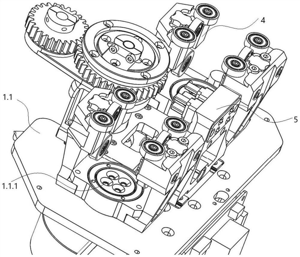
[0034] Implementation Figure 1 ~ 12 As shown, a mounted robot includes a robot body, and a walking module 1 is provided on the lower end, the lower end of the walking module 1 is provided with a base 1.1, and the lower end of the base 1.1 is connected to a lifting module 2, the lifting module 2 downstate setting There is a functional module 8.
[0035] A group or a plurality of sets of suspension units 3 are provided on both sides of the upper end of the base 1.1, and the suspension portion 3 is arranged to be integrated or the split structure is connected to the base 1.1, and the suspension portion 3 can also pass through the slide. 1.1.2 Slide the base 1.1, at which time the suspension portion 3 is provided, the suspension portion 3 on both sides is connected by an elastic mechanism, and the suspension portion 3 on both sides provides tension or thrust, so that the suspension of the sides 3 A relatively unchanged spacing can also be maintained when it is affected.
[0036] The suspension portion 3 and the base 1.1 form a suspension region which is suspended on the rail, the suspension region to accommodate the rail and the travel module 1, the walking module 1 including the drive mechanism 5 and the guide mechanism 4, the drive mechanism 5 And the guiding mechanism 4 cooperates with the walking function of the robot.
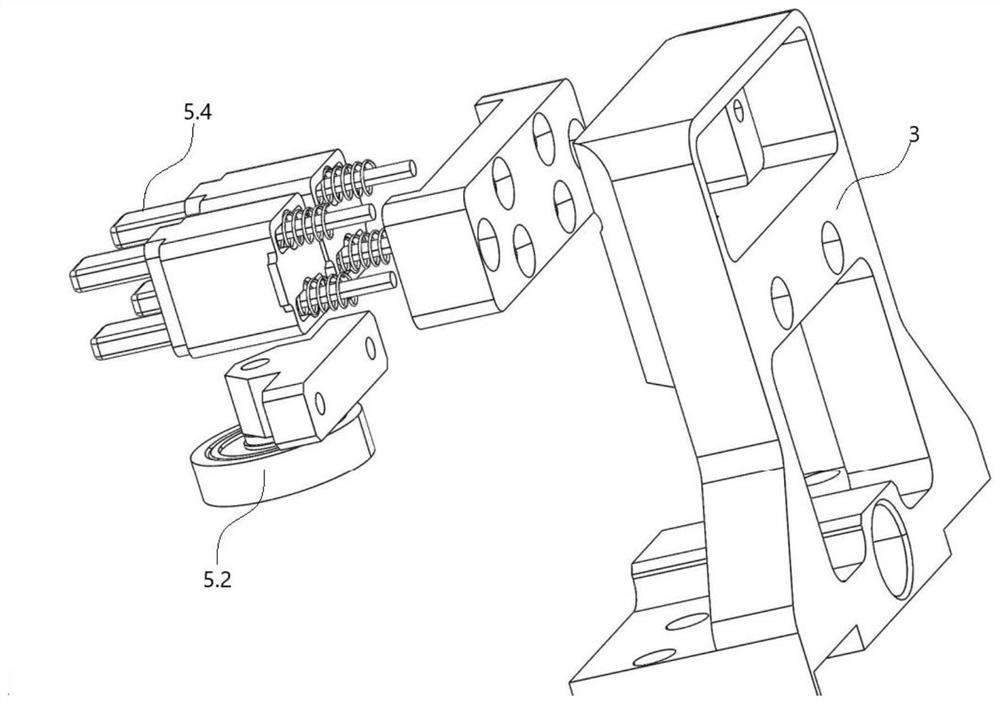
[0037] The drive mechanism 5 is provided with a walking mechanism, an electric power mechanism, and a restricted mechanism, an electric power supply mechanism and a traveling mechanism, and the electric power supply mechanism obtains power supply to the traveling mechanism, and the traveling mechanism provides power to the robot, the limit mechanism pair the travel mechanism And the power generation mechanism is lifted, the electromechanical and restricted mechanism can be disposed on the same side or side of the suspension portion 3. The traveling mechanism is provided with a walking gear 5.1 and a drive motor, and the power collector is provided with a wirebrush head 5.4, which sets a finite row group.
[0038] The suspension portion 3 is provided with a guide mechanism 4 and a drive mechanism 5 in contact with the guide groove contact with the rail side, where the row torch 4.2 is disposed vertically and the suspension portion 3, contacting the lower portion of the guide groove; auxiliary wheel group 4.3 axial direction and the suspension portion 3 vertically, contact with the upper portion of the guide groove; the guide wheel set 4.1 is disposed in parallel with the suspension portion 3, contacting the guiding groove side contact. The guide groove is also provided in the guide rail extension direction there is a slip line and a rack, and the sliding tail is in contact with the brush head 5.4, and the rack is engaged with the travel gear 5.1, the sliding line and the rack. The drive mechanism 5 is respectively provided on the top wall or side wall of the guide groove, and the drive mechanism 5 uses the combination of the rack and the travel gear 5.1 to control the grasp of the driving distance during the driving process, and using the walking gear 5.1. The combination of racks does not slip during the driver.
[0039] The electrical brush head 5.4 can be disposed as one or more electric brush head 5.4, each of which is independently provided with an elastic member, such as a compression spring, and a floating contact or electrical contact slip. The wiring is electrically connected to the drive motor. The limit race group includes a first limit wheel 5.2 and a second limit wheel 5.3. The first limit wheel 5.2 is disposed in the hanging portion 3 in which the brush head 5.4 is located and the guide groove is rotated, and the axial direction is perpendicular to the brush head 5.4, and the first limit wheel 5.2 extends from the suspension portion 3. Small than the distance extended by the brush head 5.4 to ensure that the electric brush head 5.4 is in contact with the slip torque, the bottom elastic member is not too compressed to cause damage. The second limit wheel 5.3 is disposed with the travel gear 5.1 and scrolls in contact with the guide groove, and the second limit wheel 5.3 diameter is greater than the root diameter of the walking gear 5.1, less than the walking gear 5.1. The top circular diameter is used to constrain the relative distance between the walking gear 5.1 and the rack engagement, preventing the travel gear 5.1 and the rack pressure causes damage.
[0040] The guiding mechanism 4 includes a walking wheel set 4.2, a guide wheel set 4.1, auxiliary wheel group 4.3, the auxiliary wheel group 4.2, the traveling wheel group 4.2 and the guide wheel set 4.1 are symmetrically configured to be provided on the side of the suspension portion 3, wherein the guide wheel Group 4.1 includes fixed guiding wheel set 4.1.2 and active guide wheel set 4.1.1, the active guide wheel set 4.1.1 is provided on the side of the suspension portion 3, and the fixed guide wheel set 4.1.2 is set up in the suspension portion 3. Side, position symmetrical arrangement.
[0041] A mounting hole 3.1 is also provided on the suspension portion 3, and the active guide wheel set 4.1.1 and the auxiliary wheel set 4.3 are provided with mounting 4.3.1 to cooperate with the mounting hole 3.1, and the mounting member 4.3.1 has one The blind hole is specifically manifested as an opening insertion of the mounting hole 3.1, which is an interior, a hollow structure, a mounting 4.3.1 blind hole, an elastic mechanism is provided, and the mounting member 4.3.1 is inserted into the mounting hole 3.1 is the bottom surface, from One side exposed by the mounting hole 3.1 is a front side, the remaining surface is the side, the mounting member 4.3.1 Side, a finite bump 4.3.1.2, the guide wheel or the auxiliary wheel is disposed on the limit bump 4.3.1.2, mounting parts 4.3 . 1 Other sides are provided with one or more first residual grooves 4.3.1.1. The mounting hole 3.1 is provided with a second limit groove 3.1.1 that is fitted with the limit bump 4.3.1.2, to restrict the amplitude of the mounting member 4.3.1 to the mounting hole 3.1; the mounting hole 3.1 is provided The limit screw 3.2 with the first residue 4.3.1.1 is used to restrict the magnitude of the mounting member 4.3.1 to the mounting hole 3.1.
[0042] The lifting module 2 is a telescopic device, specifically a telescopic push rod including a telescoping driving portion 2.1 and a telescopic push rod body 6, and the retractable push rod body 6 includes a screw 6.1 and a tape The telescopic arm joint 6.2, and the telescoping drive unit 2.1 including the drive motor 2.1.1 and the drive gear 2.1.2, the drive motor 2.1.1 rotate through the drive gear 2.1.2.
[0043] The telescopic arm joint 6.2 is provided to a telescopic arm of at least two groups, including at least a first telescopic arm section 6.2.1 and a second telescopic arm section 6.2.2. The first telescopic arm section 6.2.1 includes a first inner sleeve 6.2.1.2 and a first outer sleeve 6.2.1.1, a second telescopic arm section 6.2.2 includes a second inner sleeve 6.2.2.2 and the second outer The sleeve 6.2.2.1, the inner sleeve is interposed, and the outer sleeve is attached, the outer sleeve is attached to the outside of the inner sleeve. The first telescopic arm section 6.2.1 composed of the first outer sleeve 6.2.1.2 and the first outer sleeve 6.2.1.1 is formed with a receiving space of the accommodation of the second telescopic arm, which is pushed.
[0044] Specifically, the first inner sleeve 6.2.1.2 is attached to the outside of the second inner sleeve 6.2.2.2, and the second inner sleeve 6.2.2.2 is attached to the outside of the third inner casing, and push it; or first within Sockets 6.2.1.2 Take the inside of the second inner sleeve 6.2.2.2, the second inner sleeve 6.2.2.2 is attached to the inside of the third inner casing; the first outer sleeve 6.2.1.1 At the outer side of the second outer sleeve 6.2.2.1, the second outer sleeve 6.2.2.1 is attached to the outside of the third outer casing; or the first outer sleeve 6.2.1.1 is attached to the second outer sleeve 6.2 .2.1 Inside, the second outer sleeve 6.2.2.1 is attached to the outside of the third inner casing, and so on.
[0045] The finiteral assembly 7 is also provided in the telescopic arm section 6.2, the limit assembly 7 includes a limit of the inner sleeve 7.2, a limit outer casing 7.1 and a limit ring 7.3, and the outer wall is provided with a ring shape. The flange 7.2.1, the inner wall of the limit outer casing 7.1 has a accommodating groove of the accommodated annular flange, and the limit outer casing 7.1 is provided with at least one end to accommodate the openings of the annular flange, the inner casing 7.2 This opening is attached inside the limit outer casing 7.1, and the annular flange 7.2.1 is accommodated in a restricted groove 7.2 cannot continue to enter the limit outer casing 7.1, the limit ring 7.3 fixed setting in the limit The inner casing 7.2 enters the opening of the end of the limit outer casing 7.1, and the limit ring 7.3 is less than the outer diameter of the annular flange 7.2.1, the restricted ring 7.3 and the restricted outer casing 7.1 The groove is fitted to form a limit on the annular flange 7.2.1. The constrained restricted component 7 is similar to the bearing structure, the limit outer sleeve 7.2 and the limit outer casing 7.1 can be rotated relative circumference, but cannot be moved relatively axially, only axially synergistic movement.
[0046] Between the inner sleeve and the outer sleeve are connected by the limit assembly 7, in particular, the outer sleeve is fixed to the outside of the limit outer casing 7.1, and the external outer sleeve 7.1 is also provided with the guide to the inner wall of the outer sleeve. The guide grooves 6.2.4, the partial fixed sleeve of the inner sleeve, and the inner sleeve is fixed to the internal sleeve to secure the inner sleeve to secure the end of the tubing 7.2. And disposed between the outer side of the limit outer sleeve 7.2 and the inner side of the limit outer casing 7.1, thereby positioning relative to the outer sleeve and the outer sleeve, relative to the circumferential direction, specifically representing a jacket. The cartridge and the inner sleeve are synergistic to make a telescopic movement, and the inner sleeve is rotationally moving relative to the outer sleeve.
[0047] The outer sleeve outer wall extension is disposed with one or more guide grooves 6.2.4, and the outer sleeve inner wall and the guide groove 6.2.4 position are provided with a guide strip 6.2.5, and the outer sleeve is guided to each other. The groove 6.2.4 is limited to the mating of the guide strip 6.2.5, so that the movement of the outer sleeve interpolated intermediate direction is relatively fixed. Specifically, the first outer sleeve 6.2.1.1 is provided with a first guide groove, and the first outer sleeve 6.2.1.1 of the first guide groove is provided with a first guide strip; the second outer sleeve 6.2. 2.1 Outer axial direction Set the second guiding groove, the second outer sleeve 6.2.2.1 in the second guide groove is provided with a second guide strip; the first guide strip is accommodated in the second guide groove, sliding in each other, The circumferential motion between the first outer sleeve 6.2.1.1 and the second outer sleeve 6.2.2.1 acts, so that it can only do axial movement, and so on.
[0048] The inner sleeve is attached to the outer side of the screw 6.1, and there is an external thread on the screw 6.1. The inner thread is provided with an internal thread, and an outer thread is provided on the outer wall of the inner sleeve, a screw 6.1 and an inner sleeve through a thread. Connect, the first inner sleeve 6.2.1.2 and the second inner sleeve 6.2.2.2 are also threaded. Specifically, the outer wall is provided with a first external thread, and the first inner sleeve 6.2.1.2 is provided with a first internal thread, and the second internal sleeve 6.2.2.2 is provided with a second outer thread. The second internal sleeve 6.2.2.2 is provided with a second internal thread, and the first external thread is connected to the second internal thread, and in this type. When the transmission motor 2.1.1 is rotated by the transmission gear 2.1.2, the screw 6.1 is rotated relative to the first inner sleeve 6.2.1.2, and the first inner sleeve 6.2 is made due to the setting of the thread. 1.2 According to the different upper and lower movement in the direction of rotation, when the first inner sleeve 6.2.1.2 is moved to reach the limit, the screw 6.1 is relatively fixed, the screw 6.1 drives the first inner sleeve 6.2.1.2 to synergistically rotate, thus making it the first The second inner sleeve 6.2.2.2 is generated by the inner sleeve 6.2.1.2, which is pushed.
[0049] The screw 6.1 is provided as a hollow structure, and the inner is provided with a spring line 6.1.1, and the inside of the spring line 6.1.1 is attached to the screw 6.1.2, and the protective sleeve 6.1.2 can be used to the spring Line 6.1.1 Protects, when the spring line 6.1.1 telescopic, protective casing 6.1.2 can effectively prevent the spring line 6.1.1. Protective sleeve 6.1.2 Lower fixed connection finite end 6.1.3, limit end 6.1.3 Sets the finite port 6.1.3.1, the diameter of the limit port 6.1.3.1 is larger than the wire diameter of the spring line 6.1.1, smaller than the spring Line 6.1.1 Outer diameter, the spring line 6.1.1 is drawn from the limit port 6.1.3.1 while preventing the spring line 6.1.1 overall from the limit end 6.1.3. The limit end 6.1.3 is fixedly connected at the bottom of the second outer sleeve 6.2.2.1, which is specifically manifested as a limit end 6.1.3 fixedly connected to the bottom of the outer sleeve of the last telescopic arm section, and the limit end 6.1.3 is connected. The outer sleeve synergies and drives the protective sleeve together.
[0050]In order to make the overall stability of the telescopic apparatus, it is difficult to jitter, and there is a stable sleeve 6.2.3 at the bottom of each outer sleeve and the inner sleeve, reduce the sleeve of each section. The spacing between.
[0051] The protective sleeve and sleeve can be made of plastic, preferably, can also be made of carbon fiber material.
[0052] The lower end of the lifting module 2 may be provided with a functional module 8, such as an induction camera, a smart cloud station, a terminal tool, and the like, which can perform different functions by equipped with different functional modules.
[0053] Those skilled in the art will appreciate that various technical features of the above examples may perform any combination, in order to make the description, all possible combinations of various technical features in the above embodiments, however, as long as these The combination of technical features does not contradict, and should be considered as the scope of this specification.
[0054] The above embodiments are merely expressed in several embodiments of the present application, which are described more specific and detailed, but it is not understood to limit the limitation of the invention. It should be noted that for those skilled in the art, several deformations and modifications can be made without departing from the context of this application, which belongs to the scope of the present application. Therefore, the scope of protection of the patent according to the present application should be taken in the appended claims.

PUM

no PUM

Description & Claims & Application Information

We can also present the details of the Description, Claims and Application information to help users get a comprehensive understanding of the technical details of the patent, such as background art, summary of invention, brief description of drawings, description of embodiments, and other original content. On the other hand, users can also determine the specific scope of protection of the technology through the list of claims; as well as understand the changes in the life cycle of the technology with the presentation of the patent timeline. Login to view more.

Similar technology patents

Rotating Swivel Assemblies for Outriggers

ActiveUS20170071178A1reduce wear
Owner:TACO METALS LLC

Low-dragging automotive disc floating brake and braking method thereof

InactiveCN106969067AReduce drag energy lossreduce wear
Owner:WUHAN UNIV OF TECH

Classification and recommendation of technical efficacy words

Why Eureka
Try Eureka