Printing head for 3D printer
A 3D printer and print head technology, applied in the field of 3D printing, can solve problems such as melting, easy adhesion of materials, and poor heat dissipation of the print head, so as to reduce shaking, reduce material blocking, and improve printing quality.
- Summary
- Abstract
- Description
- Claims
- Application Information
AI Technical Summary
Problems solved by technology
Method used
Image

Examples
Embodiment Construction
[0036] The following is attached Figure 1-5 The application is described in further detail.
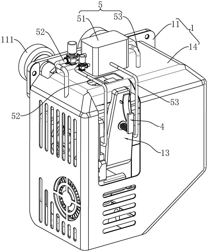
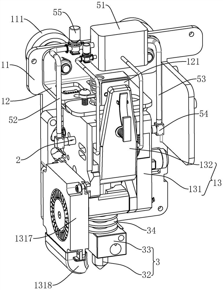
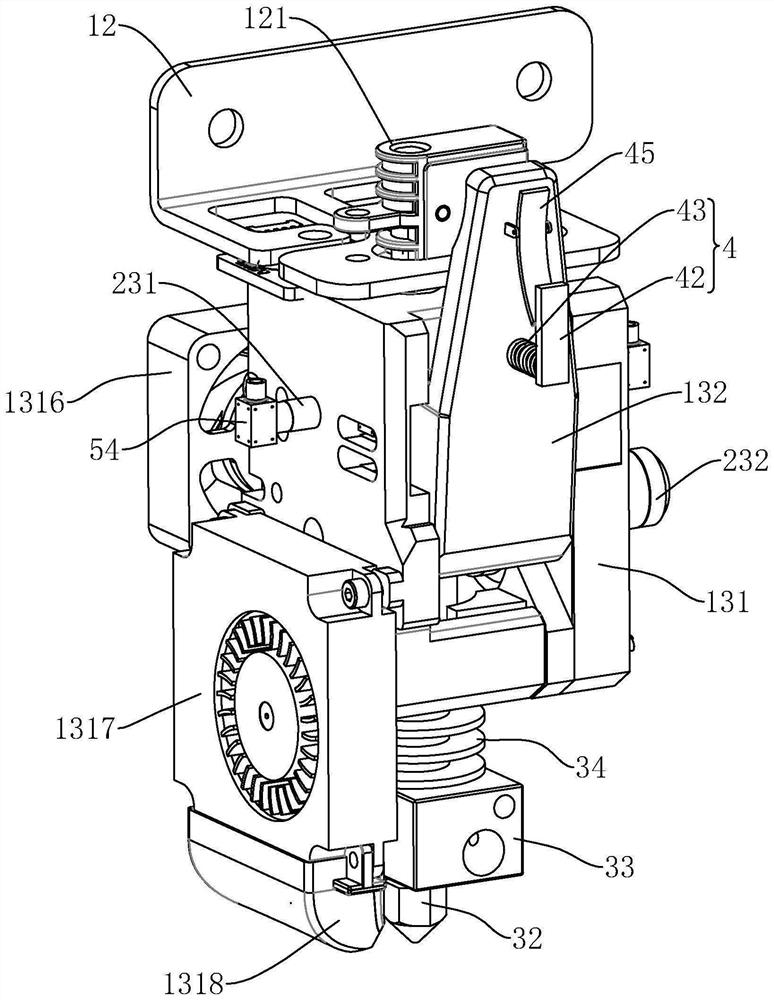
[0037] The embodiment of the present application discloses a print head for a 3D printer, referring to figure 1 , figure 2 , including a printing seat 1, a conveying mechanism 2 arranged on the printing seat 1 to convey materials, and a printing mechanism 3 arranged on the printing seat 1 to melt and print materials.
[0038] Print seat 1 comprises base 11, is fixedly connected to the installation top frame 12 of one side of base 11, is fixedly connected to the installation base 13 of installation top frame 12 lower faces and is fixedly connected to base 11 so that installation top frame 12 and installation The protective case 14 that seat 13 is covered with. A pulley 111 is rotatably connected to the side of the base 11 away from the protective cover 14, and the pulley 111 is used for sliding and walking on the slide rail. The top frame 12 is fixedly connected with a feeding gu...
PUM
 Abstract
Description
Claims
Application Information
 - R&D
- Intellectual Property
- Life Sciences
- Materials
- Tech Scout
- Unparalleled Data Quality
- Higher Quality Content
- 60% Fewer Hallucinations
Browse by: Latest US Patents, China's latest patents, Technical Efficacy Thesaurus, Application Domain, Technology Topic, Popular Technical Reports.
© 2025 PatSnap. All rights reserved.Legal|Privacy policy|Modern Slavery Act Transparency Statement|Sitemap|About US| Contact US: help@patsnap.com