

Pressing device of fireproof sandwich panel for building
A pressing device and sandwich panel technology, which is applied in the field of pressing devices, can solve the problems of large manpower consumption, many bubbles, and affecting the quality of pressing, so as to prevent random movement and ensure the effect of appearance quality
- Summary
- Abstract
- Description
- Claims
- Application Information
AI Technical Summary
Problems solved by technology
Method used
Image

Examples
Embodiment 1
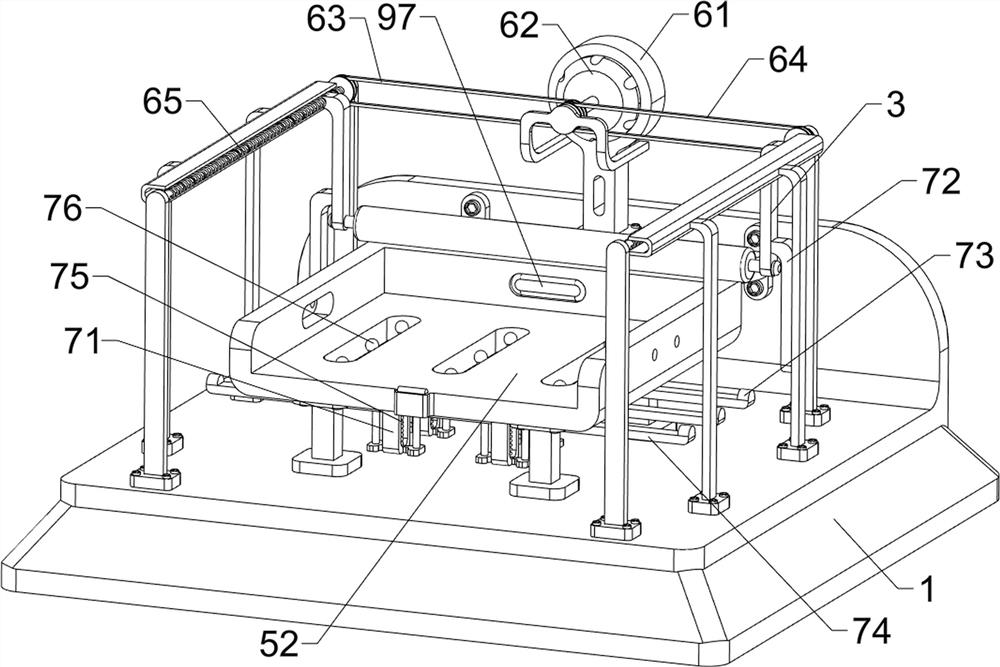
[0028] A pressing device for fire-resistant sandwich panels used in construction, such as figure 1 , figure 2 with Figure 8 As shown, it includes a base 1, a guide groove plate 2, a sliding block 3, a pressing wheel 4, a material placement mechanism 5 and a power mechanism 6. The top of the base 1 is symmetrically provided with a guide groove plate 2, and the guide groove plate 2 slides The formula is provided with a sliding block 3, the bottom of the sliding block 3 is rotatably connected with a pressing wheel 4, the top of the base 1 is provided with a material placement mechanism 5, and the rear side of the top of the base 1 is provided with a power mechanism 6.
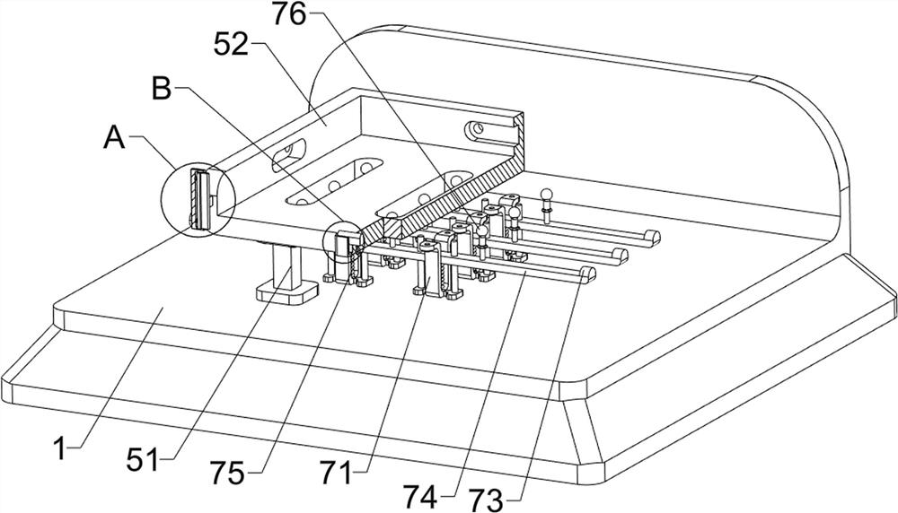
[0029] The material placement mechanism 5 includes a support frame 51, a placement trough 52, a limit block 53 and a first return spring 54, and the top of the base 1 is provided with 4 support frames 51, and the top of the support frame 51 is connected with a placement trough 52, The front side of the top of ...
Embodiment 2
[0033] On the basis of Example 1, such as Figure 3 to Figure 6 As shown, the glue bubble elimination mechanism 7 is also included, and the glue bubble elimination mechanism 7 includes a mounting frame 71, a first arc block 72, a second arc block 73, a connecting bracket 74, a second return spring 75 and a knocking post 76, the bottom of the slot plate 52 is provided with a plurality of mounting brackets 71, and a connecting bracket 74 is slidably connected between the mounting brackets 71 on the same side in the horizontal direction, and a second return spring 75 is connected between the bottom of the connecting bracket 74 and the mounting bracket 71, The top of the connecting bracket 74 is connected with a plurality of knocking columns 76, the left and right sides of the top of the connecting bracket 74 are provided with second arc-shaped blocks 73, and the outside of the lower part of the sliding block 3 is provided with a first arc-shaped block 72.
[0034]Also includes a ...
Embodiment 3
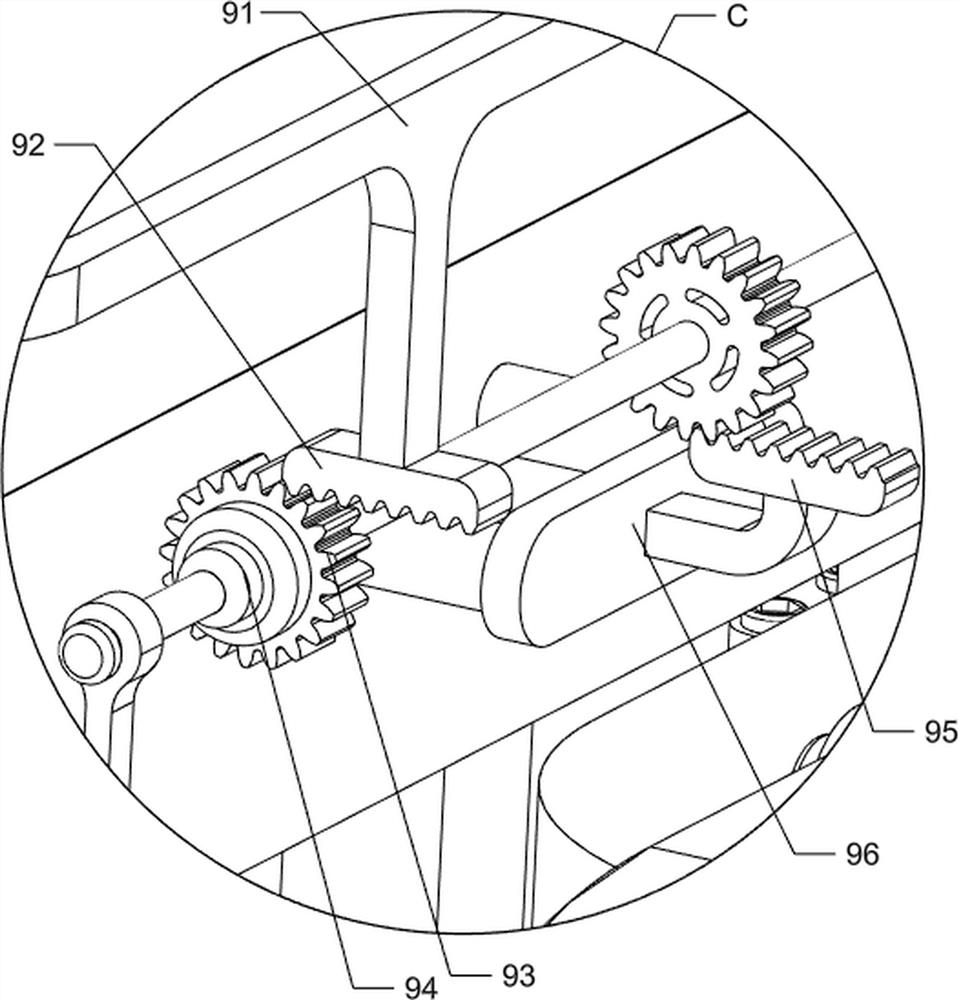
[0037] On the basis of Example 2, such as Figure 4 , Figure 7 , Figure 8 , Figure 9 with Figure 10 As shown, a discharge mechanism 9 is also included, and the discharge mechanism 9 includes a connecting frame 91, a first rack 92, a transmission gear 93, a one-way clutch 94, a second rack 95, a connecting rod 96 and a pusher plate 97 , between the rear sides of the sliding block 3 is connected with a connecting frame 91, the bottom of the connecting frame 91 is left and right symmetrically provided with a first rack 92, the rear side of the groove plate 52 is placed to be rotatably connected to a rotating shaft, and a one-way clutch 94 is arranged symmetrically on the rotating shaft , the one-way clutch 94 and the middle part of the rotating shaft are provided with a transmission gear 93, the rear side of the slotted plate 52 is slidably provided with a connecting rod 96, and the rear side of the connecting rod 96 is provided with a second rack 95, the second rack 95 an...
PUM
 Abstract
Description
Claims
Application Information