
Parachute with automatic parachute opening function

A parachute and functional technology, applied in the parachute field, can solve problems such as the inability to accurately grasp the height of the parachute and the difficulty of opening the parachute, achieving the effect of low cost and ensuring structural stability

Pending Publication Date: 2022-03-08
李天勇
View PDF0 Cites 0 Cited by
  • Summary
  • Abstract
  • Description
  • Claims
  • Application Information

AI Technical Summary

Problems solved by technology

For those who have not received skydiving training, it is very difficult to grasp the timing of opening the parachute. Passengers who have not been trained cannot accurately grasp the height of the parachute, which is a hidden danger when using a parachute

Method used


Image

  • Parachute with automatic parachute opening function
  • Parachute with automatic parachute opening function
  • Parachute with automatic parachute opening function

Examples


Embodiment 1

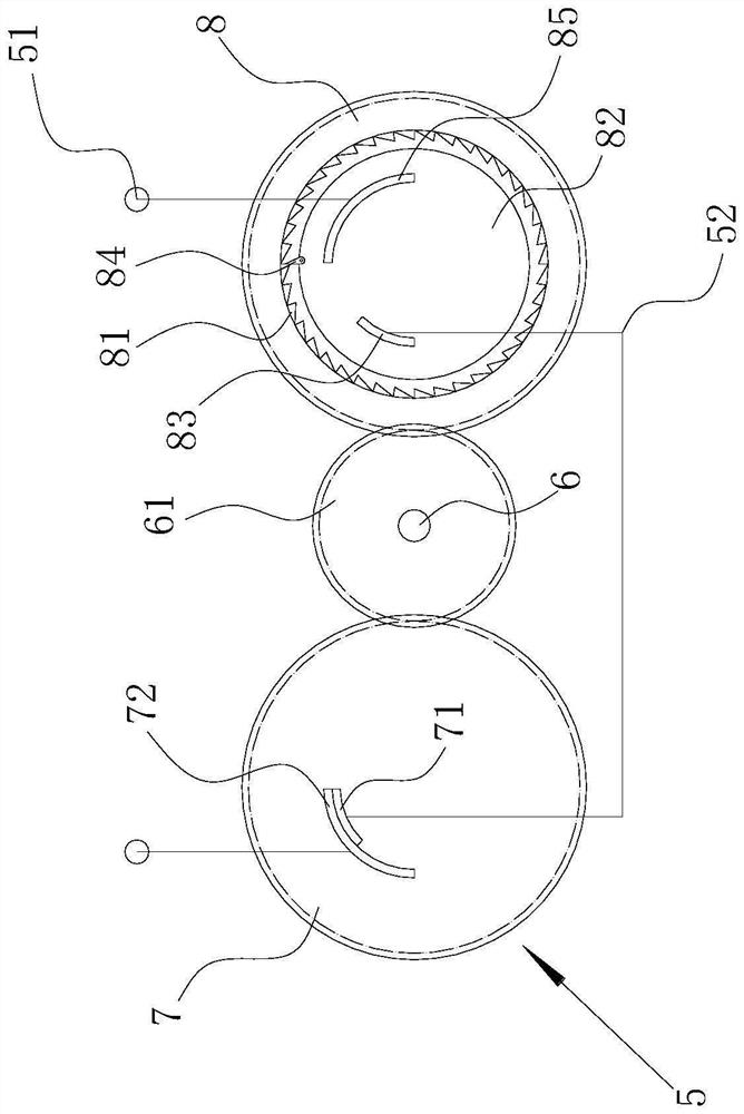
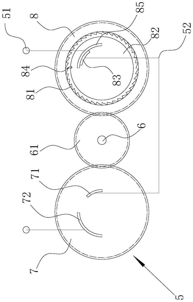
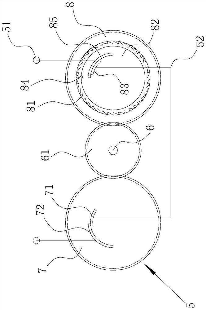
[0020] see Figure 1-Figure 5 , a parachute with automatic parachute opening function, comprising an umbrella bag 1 and a parachute body arranged on the umbrella bag 1, the parachute body includes a canopy 21 and a parachute rope 22, and the lower part of the canopy 21 is circumferentially provided with a number of up and down intervals to be inflated The annular airbag 3 in the lowest state matches the lower side edge of the canopy 21, and the annular airbags 3 are connected through the bridge passage 31 connecting all the annular airbags 3. The canopy 21 is provided with a power supply 4. The controller 5, the power supply 4, the controller 5, and the annular airbag 3 are connected in series in sequence to form a closed loop. The controller 5 includes an outer shell (not shown in the figure), and a pointer barometer is arranged in the outer shell The shaft 6 of the pointer barometer is provided with a main gear 61 that rotates with the shaft 6, the main gear 61 is arranged h...

Embodiment 2

[0024] see Figure 4 , Figure 6 , Figure 7 , a parachute with automatic parachute opening function, comprising an umbrella bag 1 and a parachute body arranged on the umbrella bag 1, the parachute body includes a canopy 21 and a parachute rope 22, and the lower part of the canopy 21 is circumferentially provided with a number of up and down intervals to be inflated The annular airbag 3 in the lowest state matches the lower side edge of the canopy 21, and the annular airbags 3 are connected through the bridge passage 31 connecting all the annular airbags 3. The canopy 21 is provided with a power supply 4. The first controller 5, the second controller 9, and the annular airbag 3 are connected in series in sequence to form a closed loop. The first controller 5 includes an outer shell, and a pointer barometer is arranged in the outer shell, and the rotating shaft of the pointer barometer is 6 is provided with a main gear 61 that rotates with the rotating shaft 6. The main gear ...


PUM


Abstract

A parachute with an automatic parachute opening function comprises a parachute canopy, a plurality of to-be-inflated annular air bags are arranged on the lower portion of the parachute canopy in the circumferential direction in an up-down spaced mode, the annular air bag located on the lowermost side is matched with the edge of the lower side of the parachute canopy, and the annular air bags are communicated through bridging channels communicating all the annular air bags. A power source and a controller are arranged on the parachute canopy, the power source, the controller and the annular air bag are sequentially connected in series to form a closed loop, the controller for triggering the air bag is designed according to the characteristic that the external air pressure in the parachuting process is reduced firstly and then rises again, and the parachute can be controlled to be automatically opened at the proper height; and the annular air bag forms a framework of the parachute canopy, so that the structural stability of the parachute after the parachute is opened can be ensured, the falling process is less influenced by weather, and the parachute canopy can be used without any additional training.

Description

technical field [0001] The invention relates to a parachute with automatic parachute opening function. Background technique [0002] Parachute is to utilize the principle of air resistance, relying on the aerodynamic speed reducer that is inflated relative to air movement. The parachute on the plane is usually used as a life-saving tool for people to safely land on the ground from the sky. For people who have not been trained in skydiving, it is very difficult to grasp the timing of opening the parachute. Passengers who have not been trained cannot accurately grasp the height of the parachute, which is a hidden danger when using a parachute. Contents of the invention [0003] The technical problem to be solved by the present invention is to provide a parachute with automatic parachute opening function, which will automatically open the parachute when the parachute opening time is reached. training can be used. [0004] In order to solve the above-mentioned technical pro...

Claims


Application Information

Patent Timeline
IPC IPC(8): B64D17/56B64D17/72
CPCB64D17/56B64D17/72
Inventor 李天勇付晓菲
Owner 李天勇
Learn More