
Crown spring terminal and assembly process thereof

An assembly process and crown spring technology, which is applied in the manufacture of coupling devices, components of connecting devices, and contact pieces, can solve the problems of high inner and outer diameter size range, inconvenient operation, gaps, etc., and achieve convenient and easy molding process Effect of operation and simplification of assembly process

Pending Publication Date: 2022-03-08
深圳特思嘉工业电子有限公司
View PDF0 Cites 0 Cited by
  • Summary
  • Abstract
  • Description
  • Claims
  • Application Information

AI Technical Summary

Problems solved by technology

[0004] After the crown spring is installed into the connecting end of the female terminal, it is necessary to close the opening of the female terminal. The fillet-shaped closure formed at the opening is likely to have a gap between the ejector pin and the main body during the injection molding process, which will cause the injection material to flow into the female terminal from the gap between the female terminal and the ejector pin

Method used


Image

  • Crown spring terminal and assembly process thereof
  • Crown spring terminal and assembly process thereof
  • Crown spring terminal and assembly process thereof

Examples


Embodiment 1

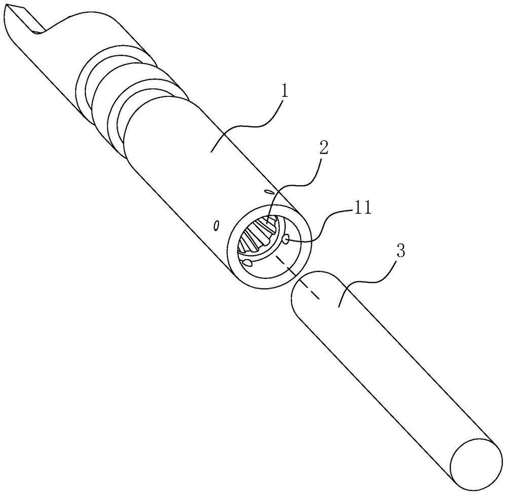
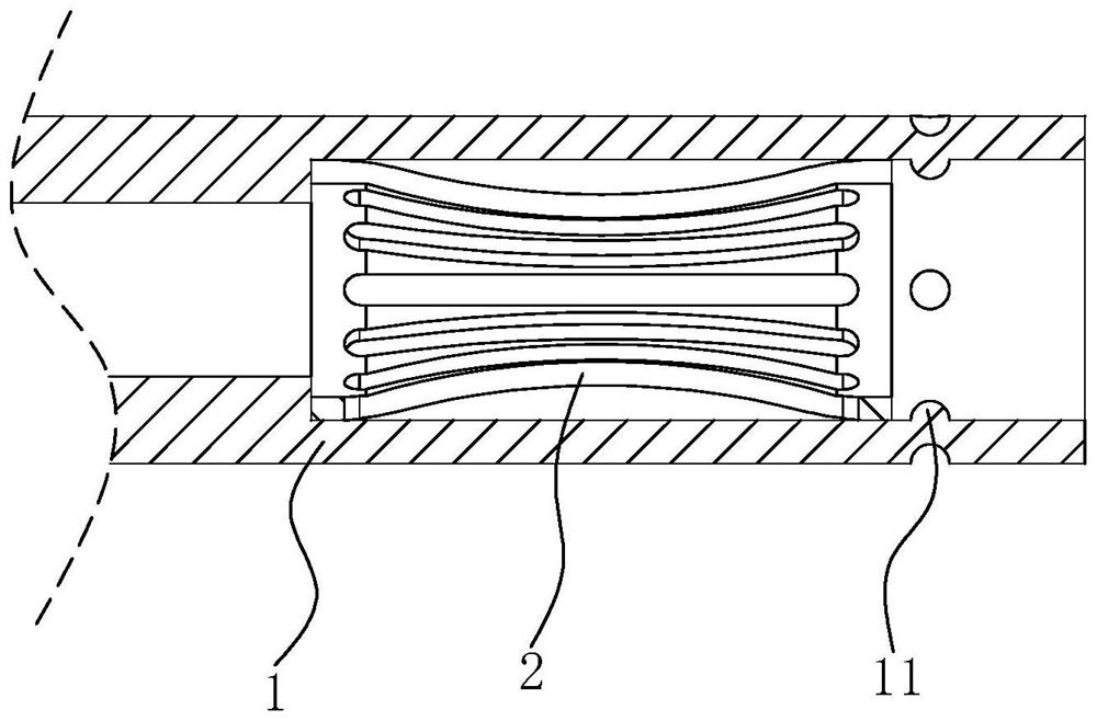
[0040] refer to figure 1 The crown spring terminal includes a female terminal 1, a male terminal 3 and a crown spring 2. The female terminal 1 and the male terminal 3 are used for mutual connection. The connecting end of the female terminal 1 is cylindrical, and the crown spring 2 is installed on the connection of the female terminal 1 In the end, the connecting end of the male terminal 3 is in the shape of a cylindrical needle, and is used for connecting in the crown spring 2. When in use, insert the connecting end of the male terminal 3 into the crown spring 2 to realize the connection between the male terminal 3 and the female terminal 1, so as to transmit current or signal.

[0041] refer to figure 1 and figure 2, the crown spring 2 is cylindrical, and the cross-section is circular, and the diameter of the crown spring 2 changes uniformly along its axial direction. In this embodiment, the diameter of the crown spring 2 gradually decreases from both ends to the middle. I...

Embodiment 2

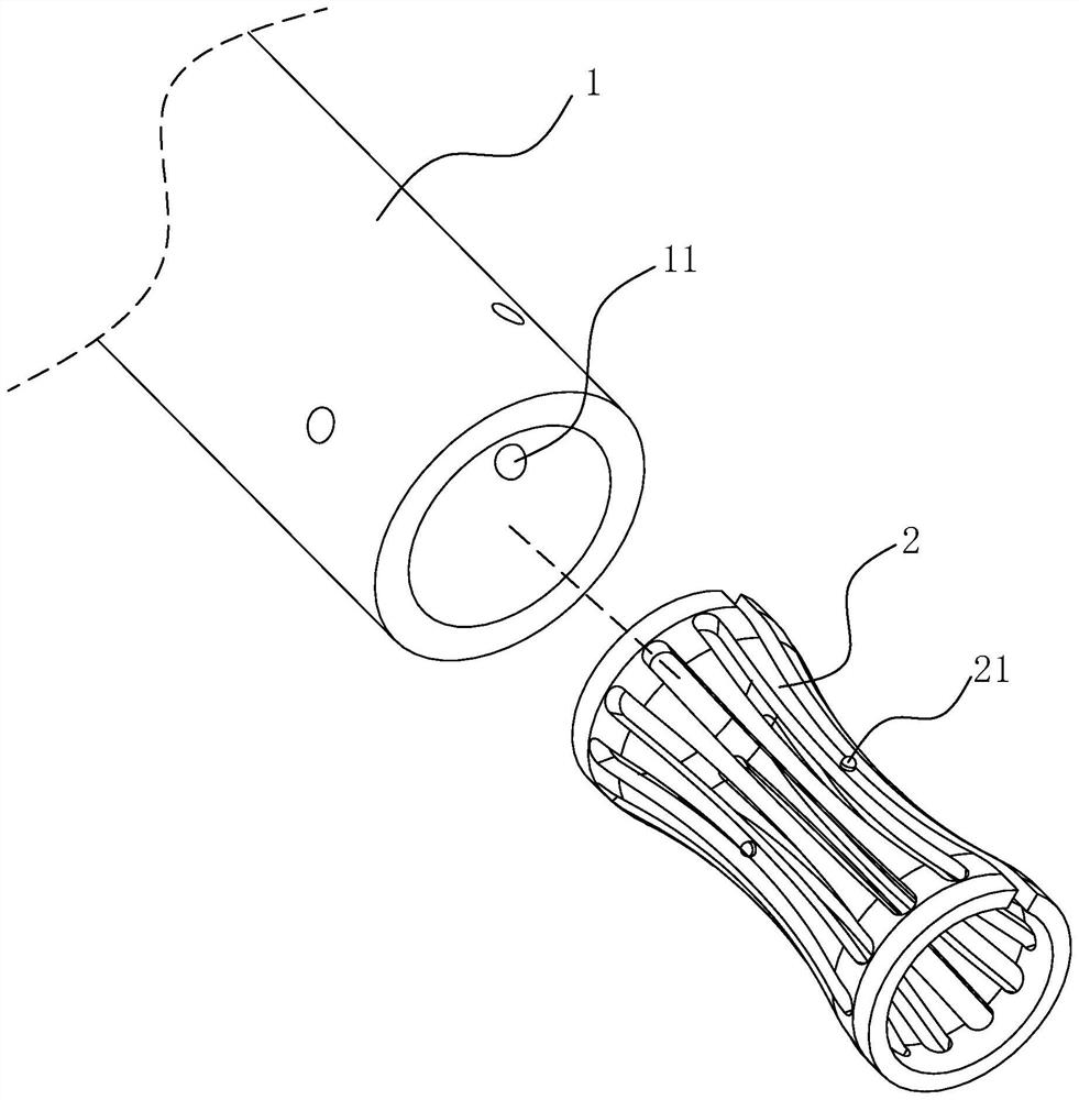
[0045] refer to image 3 The difference between this embodiment and Embodiment 1 is that the outer wall of the crown spring 2 with the smallest cross-sectional size is formed with a second protrusion 21, and several second protrusions 21 are evenly arranged around the circumference of the crown spring 2. The protrusion 21 can be integrally formed with the crown spring 2, and can also be formed by cold extrusion from the inside of the crown spring 2 after the crown spring 2 is formed. the distance between the outer walls.

[0046] When the male terminal 3 is inserted into the crown spring 2, the middle part of the crown spring 2 is opened outwards. At this time, the middle part of the crown spring 2 clamps the male terminal 3 tightly, and the second protrusion 21 is in close contact with the inner wall of the female terminal 1. , thereby effectively improving the connection strength and stability between the crown spring 2 and the male terminal 3 and the female terminal 1 .

...


PUM


Abstract

The invention relates to a crown spring terminal, and relates to the field of electric connectors, the crown spring terminal comprises a female terminal and a crown spring, the connecting end of the female terminal is cylindrical, the crown spring is arranged in the connecting end of the female terminal, a first protrusion is formed on the inner wall of the connecting end of the female terminal, and the first protrusion is located between the crown spring and an opening of the connecting end of the female terminal; and the crown spring is blocked in the connecting end of the female terminal. The invention further relates to an assembly process of the crown spring terminal. According to the invention, closing-up after the crown spring is installed in the female terminal is avoided, the assembling process of the crown spring and the female terminal is simplified, the possibility of a gap between the opening of the connecting end of the female terminal and the ejector pin in the main body injection molding process is reduced, and the effect of preventing an injection material from flowing into the female terminal as much as possible is achieved.

Description

technical field [0001] The present application relates to the field of electrical connectors, in particular to a crown spring terminal and its assembly process. Background technique [0002] The electrical connector is a device that realizes the electrical connection function. The electrical connector includes a connector terminal and two injection-molded insulating material bodies. The connector terminal includes a male terminal and a female terminal. The connecting end of the female terminal is generally cylindrical. The connecting end of the terminal is in the shape of a pin column, the female terminal is embedded in one of the main bodies, and the male terminal is connected to the other main body. The conductive contact is realized by inserting the connecting end of the male terminal into the connecting end of the female terminal, and conducts current or signal transmission. [0003] The crown spring terminal is a commonly used type of connector terminal. A crown spring...

Claims


Application Information

Patent Timeline
IPC IPC(8): H01R13/187H01R13/24H01R13/639H01R43/16
CPCH01R13/187H01R13/639H01R13/2414H01R43/16
Inventor 田子良林海龙
Owner 深圳特思嘉工业电子有限公司
Learn More