Apparatus for fast cone beam tomography and extended SAD imaging in radiation therapy

A radiation cone and projected image technology, which is applied in the fields of radiodiagnostic instruments, radiotherapy, X-ray/γ-ray/particle irradiation therapy, etc. It can solve the problems of being unable to track the target volume and being invisible

Pending Publication Date: 2022-03-11
VARIAN MEDICAL SYST INT AG
View PDF3 Cites 0 Cited by
  • Summary
  • Abstract
  • Description
  • Claims
  • Application Information

AI Technical Summary

Problems solved by technology

For treatments utilizing a rotating gantry (such as in Volumetric Modulated Arc Therapy (VMAT, ), Intensity Modulated Radiation Therapy (IMRT), Stere

Method used


Image

  • Apparatus for fast cone beam tomography and extended SAD imaging in radiation therapy
  • Apparatus for fast cone beam tomography and extended SAD imaging in radiation therapy
  • Apparatus for fast cone beam tomography and extended SAD imaging in radiation therapy

Examples


Embodiment Construction

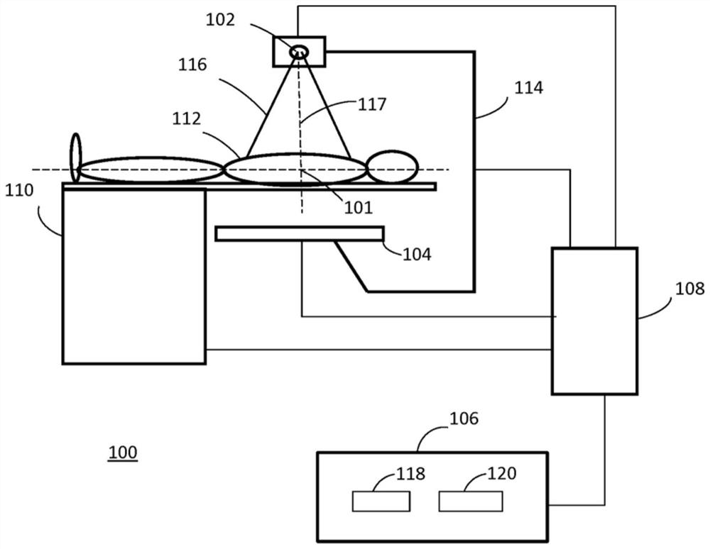
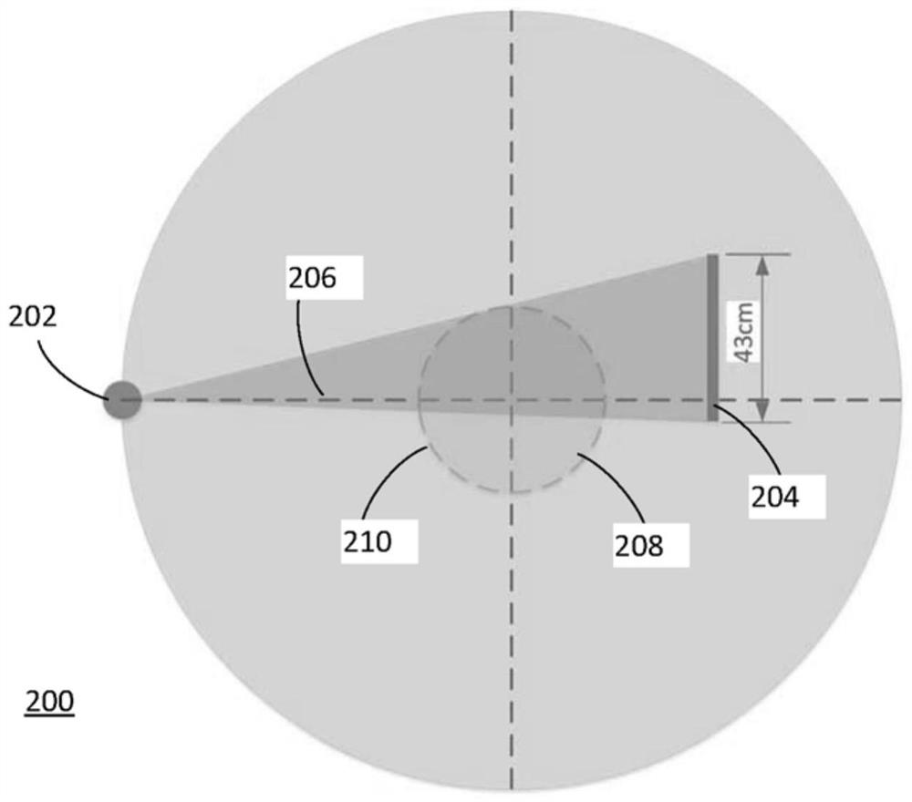
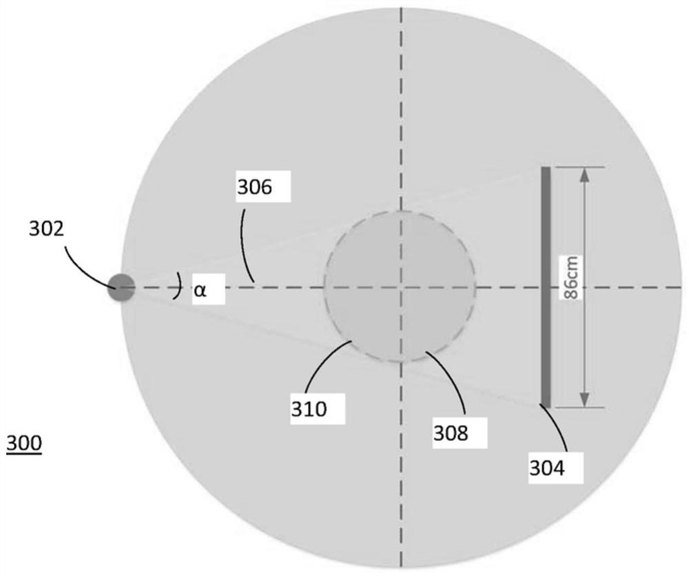
[0017] refer to Figure 1—Figure 5D , describing a CBCT system and a radiation therapy machine including the CBCT system. In general, an example CBCT system includes a cone beam radiation source and an area detector operable to acquire projection images of a large object, or operable to acquire projection images encompassing a reference volume located remote from the isocenter of the system . The area detector and cone beam radiation source are capable of acquiring projection images at approximately 180 degrees plus a fan angle to provide a complete data set for CBCT reconstruction to generate an image volume with a field of view (FOV) of at least approximately 20 centimeters . Alternatively or additionally, the area detector and cone beam radiation source are capable of acquiring projection images at any gantry angle covering a reference volume located approximately 10 cm or more from the isocenter of the system. As used herein, the term "gantry angle" which is used interc...


PUM


Abstract

A cone beam computed tomography (CBCT) system employs a large area detector and a cone beam radiation source to allow projection images to be acquired at approximately 180 degrees plus fan angles to provide a complete data set for CBCT reconstruction to generate an image volume having a field of view (FOV) of at least approximately 20 cm.

Description

technical field [0001] The present disclosure relates generally to radiation imaging and therapy. In particular, various embodiments of cone beam computed tomography (CBCT) systems including large or very large image detectors and radiotherapy machines including the CBCT systems are described. Background technique [0002] Cone beam computed tomography is known and has proven to be an invaluable tool for many clinical applications. When performing CBCT, the cone beam radiation source and image detector are rotated around the subject to acquire multiple projection images. The acquired projection images are reconstructed using computer software to generate tomographic images that can be displayed or visualized in two-dimensional (2D) image slices or three-dimensional (3D) image volumes of the subject. [0003] Image artifacts, distortions in the reconstructed image are common in CBCT. Some of the most severe image artifacts in CBCT are caused by patient motion or movement o...

Claims


Application Information

Patent Timeline
IPC IPC(8): A61N5/10
CPCA61N5/1049A61N5/103A61N5/1045A61N2005/1054A61N2005/1061A61N2005/1092A61B6/032A61B6/4078A61B6/4085A61B6/4233A61B6/4266A61B6/469A61B6/482A61B6/4241A61B6/5282A61B90/10A61B2090/101A61B6/035A61B6/0407A61B6/4007A61N5/1081
Inventor D·莫尔夫M·阿姆斯图兹S·凯勒
Owner VARIAN MEDICAL SYST INT AG
Why Eureka
Try Eureka