Device and method for tomography and digital x-ray radiography of a flexible riser

a flexible riser and x-ray radiography technology, applied in the field of mobile x-ray radiography apparatus, can solve the problems of stray radiation, unfavorable safety and feasibility of applying the known art apparati, and inability to turn, so as to achieve less stray radiation

Inactive Publication Date: 2003-07-31
STATOIL ASA PETRO SA (NO)
View PDF0 Cites 16 Cited by
  • Summary
  • Abstract
  • Description
  • Claims
  • Application Information

AI Technical Summary

Benefits of technology

0011] Other important advantages of the invention is that the rather narrow beam fan neccesary to radiate only a part of the riser end fixture (about one half of the cross-section of the riser end fixture) will incur less stray radiation. This narrow fan does not pass through all parts of the riser end fixture at a time, but this lack is compensated for by rotating the entire source and receiver system about the axis of the riser end fitting in order to reach all parts and all projection angles through the riser end fitting.

Problems solved by technology

Also, stray radiation may arise in the side areas where the radiation is near tangential to the pipe.
However, for radiometric inspection of a flexible riser in situ, i.e. on a producing production platform, the apparati of the known art are not safely nor feasibly applied.
One may not turn an installed and producing riser except with great effort, which may destroy the riser pipe end.
There may not be structural support for such apparatus of the known art, and certainly not for the shielding of apparatis of the known art, to protect workers on the platform.
Reducing the radiation shield thickness would incur a risk of unacceptably high radiation doses for the workers.
Also, measurements conducted by sensors near the hangoff area of the riser may be negatively affected by the stray radiation from the instruments of the known art, as they radiate past the periphery of the inspected pipe.

Method used


Image

  • Device and method for tomography and digital x-ray radiography of a flexible riser
  • Device and method for tomography and digital x-ray radiography of a flexible riser
  • Device and method for tomography and digital x-ray radiography of a flexible riser

Examples


Embodiment Construction

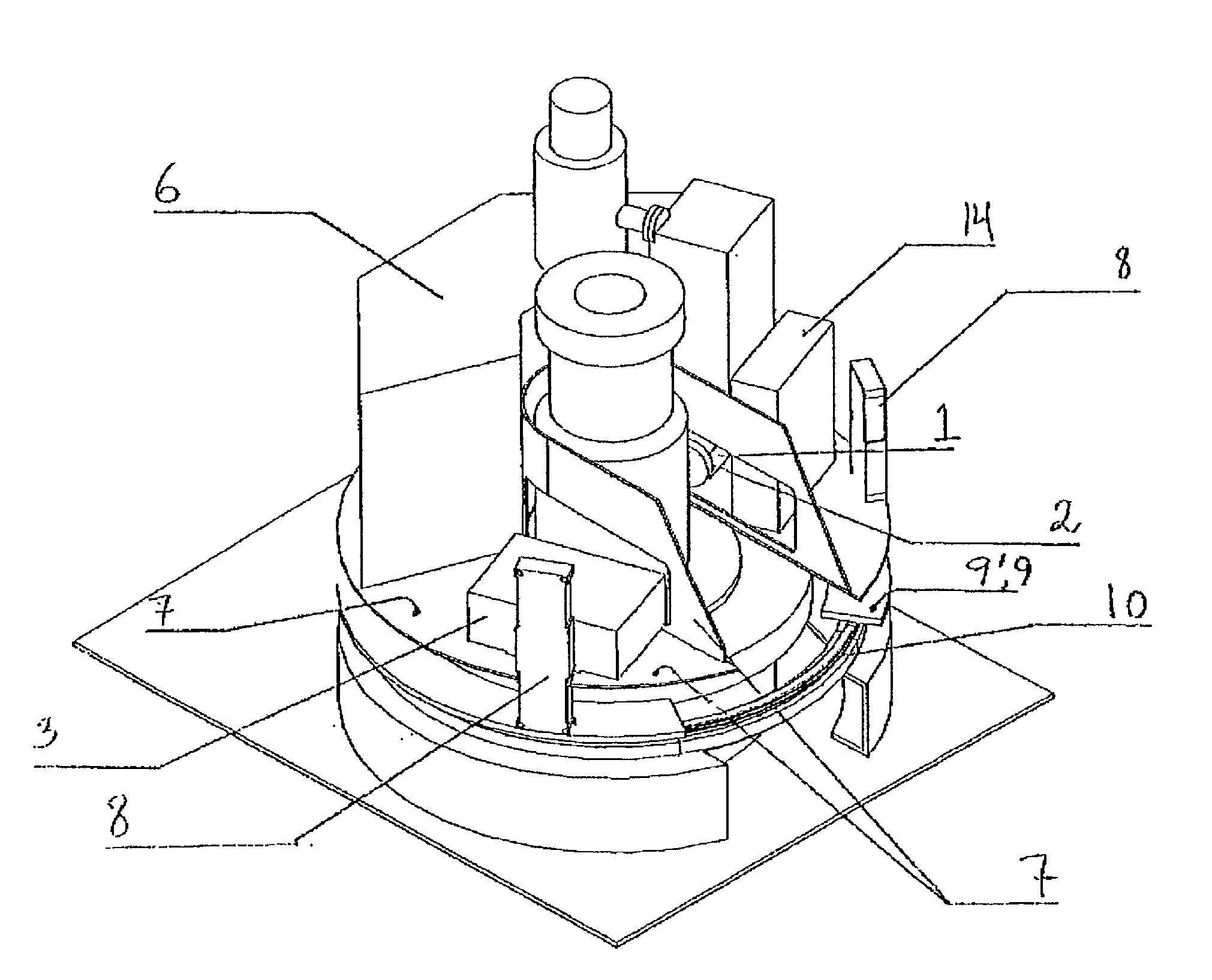
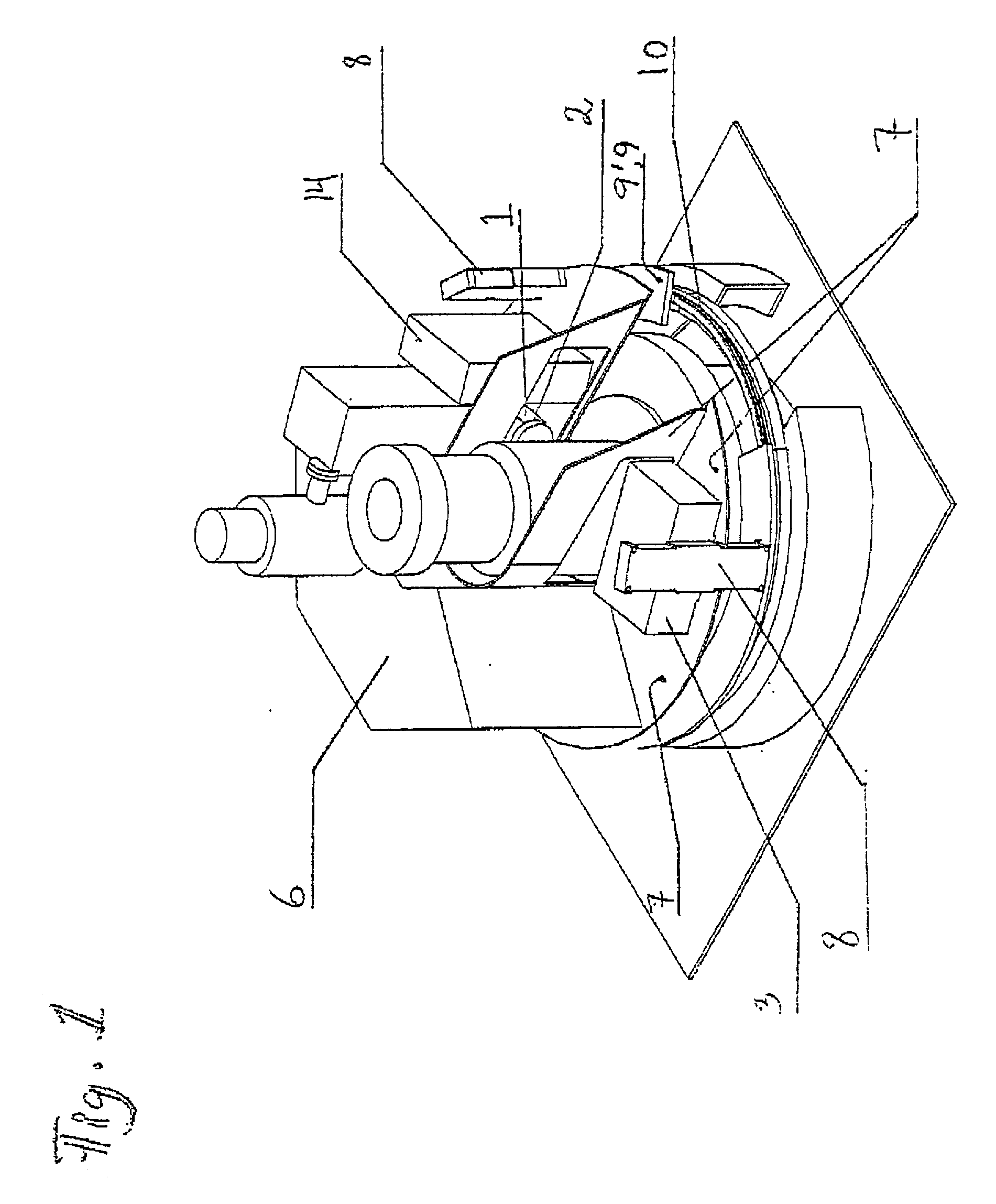
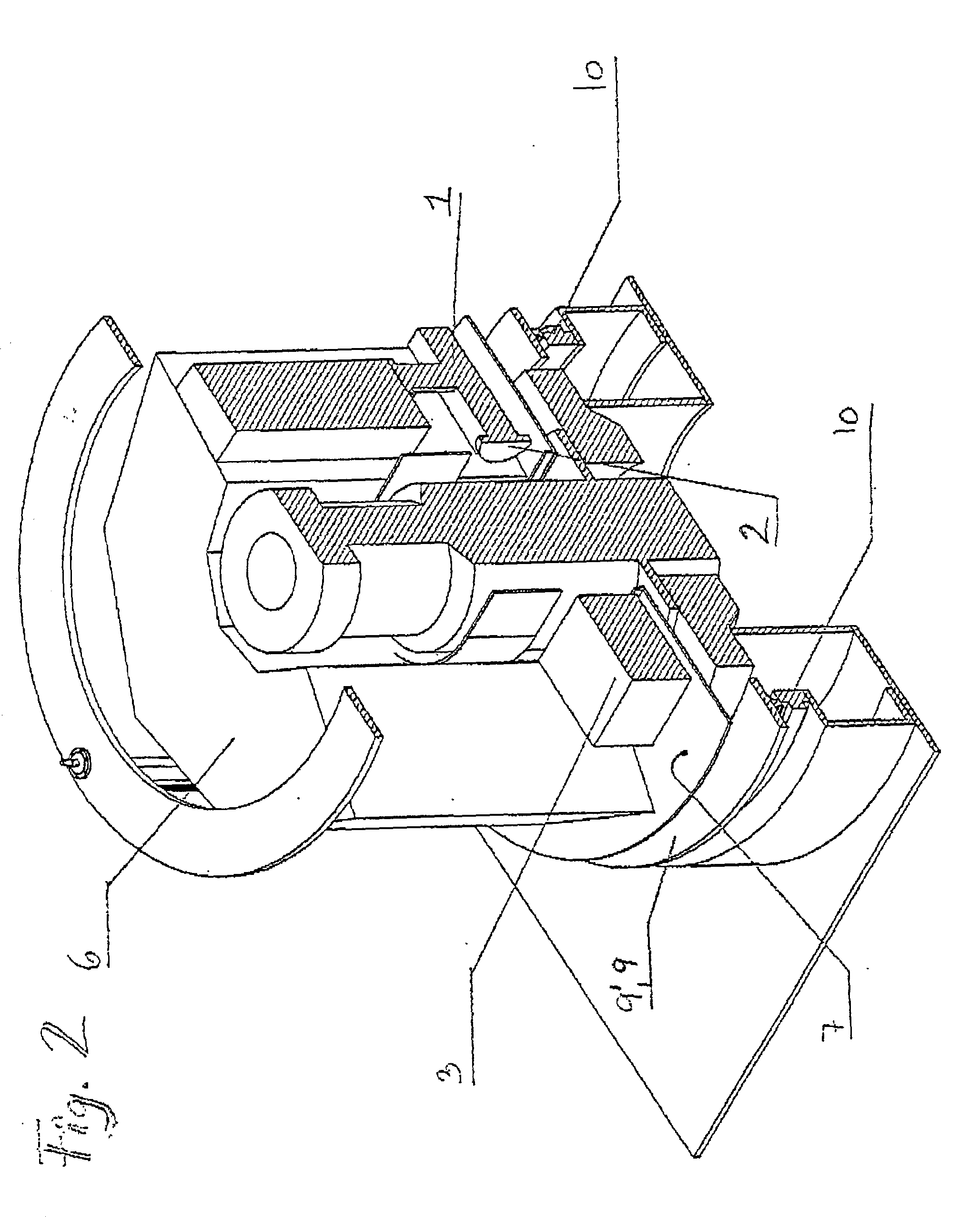
[0022] FIG. 1 illustrates a preferred embodiment of the intention on a mounting bracket attached around a riser end fitting. The riser end fitting is here surrounded by a klystron (6) connected to and powering an x-ray source (1) which radiates s-rays of about 6 to 9 MeV through a selected section of a riser end fitting extending vertically. The source may be a linear accelerator of the S-band type or the X-band type, or a cyclotron. Passive sources carrying nuclear isotopes do not have sufficient energy for the particular purpose of the invention, which may require a radiation of about min. 1000 Rad / min. A linear sensor array (3) on the opposite side of the source can be seen in FIG. 1. The apparatus of the invention is arranged rotatable on a circular rail (10) for being moved about the axis of the riser end fitting, and is designed movable to other riser end fittings one by one for analyzing each particular end fitting instead of permanent installation. Typically, a petroleum pro...


PUM

PropertyMeasurementUnit
thicknessaaaaaaaaaa
weightaaaaaaaaaa
flexibleaaaaaaaaaa

Abstract

An x-ray radiography tomography device for a flexible riser, particularly a riser end fitting on a riser hangoff block on a petroleum platform, the x-ray radiography device comprising the following features: a) an x-ray source (1) of about 6 to 9 MeV arranged for directing said x-rays generally through an adjacent and an opposite sidewall portion of said riser; b) a collimator (2) arranged between said x-ray source (1) and said sidewall of said riser pipe being adjacent to said source (1), said collimator (2) arranged for directing radiation said x-rays in a beam fan generally extending in a plane perpendicular to a long axis of the riser; c) a sensor array (3) for receiving said x-ray beam fan after passage throug said riser pipe, said array comprising a plurality of scintillation detectors (30), said sensor array (3) arranged generally opposite of said source (1) with respect to said riser tube, and extending along a line extending generally perpendicular to said axis of said riser; d) an internal frame (7) for rotating the x-ray source (1), the collimator (2) and the sensor array (3) generally about said axis of said riser, said framework arranged on a circular guide rail (10) mounted around said flexible riser hangoff block.

Description

TECHNICAL AREA OF THE INVENTION[0001] The invention relates to a device for x-ray radiography of a flexible riser for a petroleum platform for producing petroleum fluids from a well in the seabed. More particularly, the invention relates to a mobile x-ray radiography apparatus for flexible risers, and a method for conducting the x-ray radiography using such an apparatus. The apparatus for X-ray tomography and digital radiography is used and the method is applied at both the parts of the riser constituting endpieces, a so-called end fitting, but the apparatus may be modified for use on the flexible riser portions, both the dry part extending above the sea, or even the submerged part of the flexible riser. The purpose of the invention is to provide information about the integrity of the fine structure of the riser to prevent leakage and damage due to mechanical deformation or chemical alterations.KNOWN ART[0002] U.S. Pat. No. 4,725,963 describes an apparatus and a method for non-conta...

Claims


Application Information

Patent Timeline
Patent Type & Authority Applications(United States)
IPC IPC(8): G01N23/04G01N23/06
CPCG01N23/046G01N2223/419G01N23/06G01N23/083
Inventor DAALAND, ALFSMITH, CHARLES R.HAGEMANN, CHRISTIAN FREDERIK OTTO
Owner STATOIL ASA PETRO SA (NO)
Why Eureka
Try Eureka