Metal pipe finish machining treatment equipment

A technology for processing equipment and metal pipes, which is applied to metal processing equipment, metal processing mechanical parts, shearing machine equipment, etc., can solve the problems of unsuitable support devices and no debris collection and processing, and achieves simple structure, convenient use and convenience. effect used

Inactive Publication Date: 2022-03-11
谢森涛
View PDF0 Cites 0 Cited by
  • Summary
  • Abstract
  • Description
  • Claims
  • Application Information

AI Technical Summary

Problems solved by technology

[0004] The purpose of the present invention is to solve the shortcomings of the existing metal pipe finish processing equipment. When cutting, the supporting device is not suitable for metal pipes of different lengths, and there is no function of collecting and processing the cut debris. A metal pipe finish processing equipment is proposed

Method used


Image

  • Metal pipe finish machining treatment equipment
  • Metal pipe finish machining treatment equipment
  • Metal pipe finish machining treatment equipment

Examples


Embodiment 1

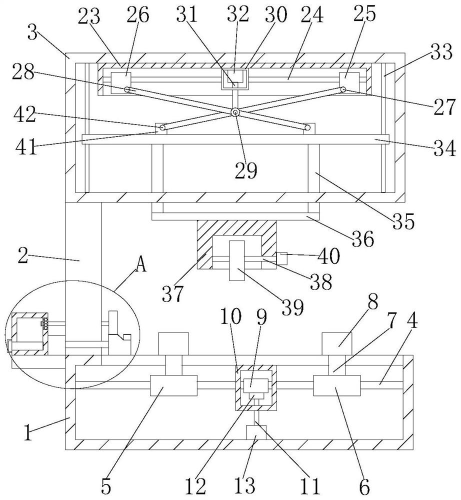
[0028] refer to Figure 1-5 , a metal pipe finish processing equipment, comprising a base 1, a support 2 is fixedly installed on one end of the top of the base 1, a top frame 3 is fixedly installed on the top of the support 2, a driving screw 4 is connected to the base 1 for rotation, and the driving screw 4 is threadedly connected with a first sleeve 5 and a second sleeve 6, and both of the first sleeve 5 and the second sleeve 6 are provided with threaded holes, the screw direction of the two threaded holes is opposite to that of the driving screw 4, the first Both the sleeve 5 and the second sleeve 6 are fixedly connected with the drag strip 7, and one end of the two drag strips 7 is fixedly connected with an arc-shaped support 8, and the top of the base 1 is provided with a long hole, and the two drag strips 7 are all movable in the long hole, the driving screw 4 is fixedly connected with the worm rod 9, the top inner wall of the base 1 is fixedly installed with a limit fra...

Embodiment 2

[0039] refer to Figure 1-5, a metal pipe finish processing equipment, including a base 1, the top end of the base 1 is welded with a support 2, the top of the support 2 is welded with a top frame 3, and the base 1 is rotatably connected with a drive screw 4, the drive screw 4 is threadedly connected with a first sleeve 5 and a second sleeve 6, and both of the first sleeve 5 and the second sleeve 6 are provided with threaded holes, the screw direction of the two threaded holes is opposite to that of the driving screw 4, the first Both the sleeve 5 and the second sleeve 6 are welded to connect the drag strip 7, and one end of the two drag strips 7 is welded and connected with an arc-shaped support 8, and the top of the base 1 is provided with a long hole, and the two drag strips 7 are all movable in the long hole, the worm rod 9 is welded on the drive screw 4, the limit frame 10 is welded and installed on the top inner wall of the base 1, the bottom of the limit frame 10 is con...


PUM


Abstract

The invention belongs to the technical field of metal pipe machining, and particularly relates to metal pipe finish machining equipment which comprises a base, a support is mounted at one end of the top of the base, a top frame is mounted at the top of the support, a driving screw is rotationally connected into the base, and a first sleeve and a second sleeve are in threaded connection to the driving screw. Threaded holes are formed in the first sleeve and the second sleeve, the spiral direction of the two threaded holes is opposite to that of the driving screw, dragging pieces are fixedly connected to the first sleeve and the second sleeve, one ends of the two dragging pieces are fixedly connected with arc-shaped supports, a long hole is formed in the top of the base, and the two dragging pieces move in the long hole. A worm is fixedly connected to the driving screw, a limiting frame is fixedly installed on the inner wall of the top of the base, a driving rod is rotationally connected to the bottom of the limiting frame, and a turbine is fixedly connected to one end of the driving rod. The device is simple in structure, metal pipes with different lengths can be supported, dust and chippings can be collected and treated, and people can use the device conveniently.

Description

technical field [0001] The invention relates to the technical field of metal pipe processing, in particular to a metal pipe finish processing equipment. Background technique [0002] Metal pipe is a common industrial product, mainly used for the transportation of high-pressure fluid. It specifically includes steel pipes, cast iron pipes, non-ferrous metal pipes, metal wires, etc. Among them, steel pipes are divided into two types: seamless steel pipes and welded steel pipes. Metal pipes have the advantages of good heat resistance, non-combustibility, small property changes with temperature changes, high mechanical strength, and not easy to age. Therefore, metal pipes can adapt to harsh working environments. [0003] In the existing metal pipe finish processing equipment, the support device is not suitable for metal pipes of different lengths during cutting, and there is no function of collecting and processing the cut debris. Contents of the invention [0004] The purpos...

Claims


Application Information

Patent Timeline
Patent Type & Authority Applications(China)
IPC IPC(8): B23D21/00B23Q3/00B23Q11/00
CPCB23D21/00B23Q3/00B23Q11/0046B23Q2703/10
Inventor 谢森涛梁云招
Owner 谢森涛
Why Eureka
Try Eureka