Eureka AIR delivers breakthrough ideas for toughest innovation challenges, trusted by R&D personnel around the world.

Cover clamping device of glue binding machine

A clamping device, glue binding machine technology, applied in book binding, adhesive for binding, sustainable manufacturing/processing, etc., can solve problems such as high scrap rate, high cost, alignment error, etc. Experience, the effect of improving the sense of luxury and yield

Active Publication Date: 2022-03-11
昆明爱邦机电制造有限公司
View PDF8 Cites 0 Cited by
  • Summary
  • Abstract
  • Description
  • Claims
  • Application Information

AI Technical Summary

Problems solved by technology

[0006] The present invention provides a clamping device for the cover of a glue binding machine, which solves the problems of defective products in glue binding machines without an indentation mechanism, alignment errors, high cost, and high scrap rate in glue binding machines with an indentation mechanism in the prior art.

Method used


Image

  • Cover clamping device of glue binding machine
  • Cover clamping device of glue binding machine
  • Cover clamping device of glue binding machine

Examples


specific Embodiment 1

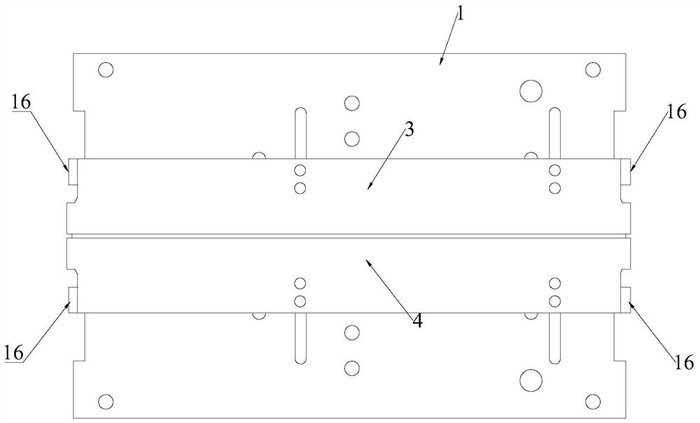
[0055] Such as figure 1 , Figure 8 As shown, the cover clamping device of the glue binding machine in this embodiment includes a first bottom plate 1, a second bottom plate 2, a first shaping block 3, a second shaping block 4, a clamping motor 5 and a clamping motor transmission structure , lifting motor 6 and lifting motor transmission structure. Wherein, the first base plate 1 is located above the second base plate 2 , and the first shaped block 3 and the second shaped block 4 are located above the first base plate 1 .

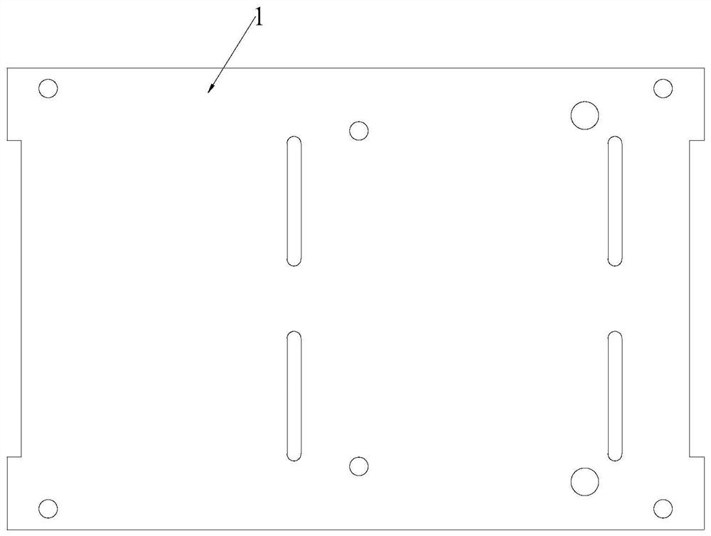
[0056] In this example, see image 3 with Figure 4 , the first bottom plate 1 is a rectangular plate structure, and the second bottom plate 2 is a rectangular frame structure, that is, the second bottom plate 2 is a hollow structure in the middle. The position of the first base plate 1 is fixed, and the first base plate 1 is connected to the second base plate 2 through four lift positioning shafts 7 , which are located at four corners below the first b...

specific Embodiment 2

[0071] When only one side of the cover needs to be indented, one of the shaping blocks, in this embodiment, the second shaping block is fixedly connected to the first bottom plate, and the second shaping block is no longer provided with movable connecting rods and corresponding gears. rack structure. It is only necessary to set the movable connecting rod and the corresponding rack and pinion structure on the first sizing block, wherein the first sizing block, the movable connecting rod and the corresponding rack and pinion structure, the first sizing block and the movable connecting rod The connection structure is the same as that in the first embodiment.

[0072]In the above-mentioned specific embodiment 1 and specific embodiment 2, the lifting of the second bottom plate is realized by a structural combination of a lifting motor, a gear, a cam, and the like. Since the first bottom plate is fixed, through the lifting of the second bottom plate, the outer end of the two shaped...

specific Embodiment 3

[0074] The cover clamping device of the glue binding machine in this embodiment includes a first bottom plate 1 and a second bottom plate 2 , and the second bottom plate is controlled to lift up and down by a liftable X-shaped support structure 24 . In this embodiment, both the first bottom plate and the second bottom plate are plate-shaped structures without hollow parts. Two support plates and a clamping motor transmission structure are arranged under the second bottom plate, and the specific structure is the same as that of the first embodiment. The bottom end of the movable connecting rod 16 is fixedly connected to the rack 20, and the top end is movably connected to the side of the outer end of the shaping plate.

[0075] Wherein, an X-shaped support structure 24 is arranged between the first base plate 1 and the second base plate 2, and the X-shaped support structure includes an upper beam fixedly installed on the bottom end of the first base plate, a lower beam fixed on...


PUM


Abstract

The cover clamping device of the glue binding machine comprises a first bottom plate and a second bottom plate, the shaping block is positioned above the first bottom plate; the shaping blocks comprise a first shaping block and a second shaping block, and at least one shaping block is movable; the shaping block is controlled by a clamping motor transmission structure to move left and right; the outer side end of the shaping block is controlled to rise and fall through a lifting structure; and the movable connecting rod is movably connected with the shaping block. The movable connecting rods are driven by the clamping motor, the gear rack and the like to move towards or away from each other, and the two movable shaping blocks are driven to move towards or away from each other, so that a clamping function is realized; when the lifting motor is controlled to lift the second bottom plate, the outer sides of the two movable shaping blocks are driven to be lifted, and the cover creasing function is achieved through the clamping action of the clamping motor. By means of the cover clamping device of the cementing machine, the high-grade feeling and the yield of cementing books and periodicals are improved, and meanwhile the comfortable experience feeling of book and periodical reading users is improved.

Description

technical field [0001] The invention relates to the technical field of indentation processing on the cover of a glue binding machine, and more specifically relates to a clamping device for the cover of a glue binding machine. Background technique [0002] The existing glue binding machines are usually divided into two types, one is the glue binding machine without indentation mechanism, and the other is the glue binding machine with indentation mechanism. [0003] For the perfect binding machine without indentation mechanism, if only the perfect binding machine is used alone and does not match other equipment, then there are two situations in the perfect bound books and periodicals. Compared with the products of big factories, there is one element missing, which is not the products bound by regular printing factories; the professionalism and texture are not as good as the products that have been indented; the second is that the books and periodicals have not been indented. ...

Claims


Application Information

Patent Timeline
Patent Type & Authority Applications(China)
IPC IPC(8): B42C9/00B42C11/04
CPCB42C9/00B42C9/0012B42C11/04Y02P70/50
Inventor 王家晶李平山杨彪
Owner 昆明爱邦机电制造有限公司
Why Eureka
Eureka Blog
Learn More