Fabricated steel reinforced concrete column-steel reinforced concrete beam joint with inner and outer steel sleeves

A prefabricated, steel sleeve technology, applied in columns, piers, pillars, etc., can solve the problems of complex connection of beam-column joints of reinforced concrete

Pending Publication Date: 2022-03-11
GUANGZHOU UNIVERSITY
View PDF0 Cites 0 Cited by
  • Summary
  • Abstract
  • Description
  • Claims
  • Application Information

AI Technical Summary

Problems solved by technology

[0005] The purpose of the present invention is to overcome the shortcomings of the existing prefabricated steel concrete beam-column joint connection, provide a prefabricated steel concrete beam-column joint connection method, combined with the construction characteristics of prefabricated assembled buildings, use high-strength bolts and welding to ensure the connection Effectiveness, it can effectively solve the problem of complex connection of steel concrete beam-column joints, not only the construction is simple, can improve the construction efficiency, and only a small amount of cast-in-place is needed on site, which can effectively reduce the construction period

Method used


Image

  • Fabricated steel reinforced concrete column-steel reinforced concrete beam joint with inner and outer steel sleeves
  • Fabricated steel reinforced concrete column-steel reinforced concrete beam joint with inner and outer steel sleeves
  • Fabricated steel reinforced concrete column-steel reinforced concrete beam joint with inner and outer steel sleeves

Examples


Embodiment approach

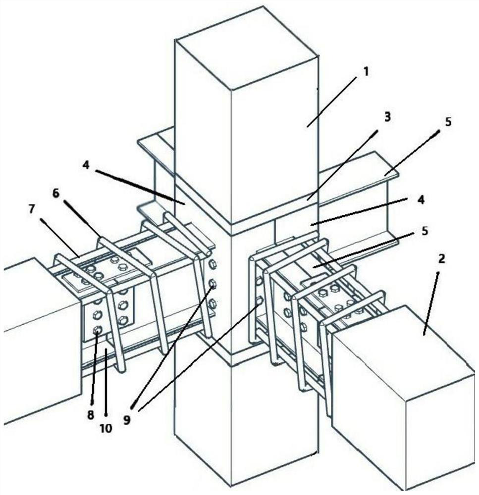
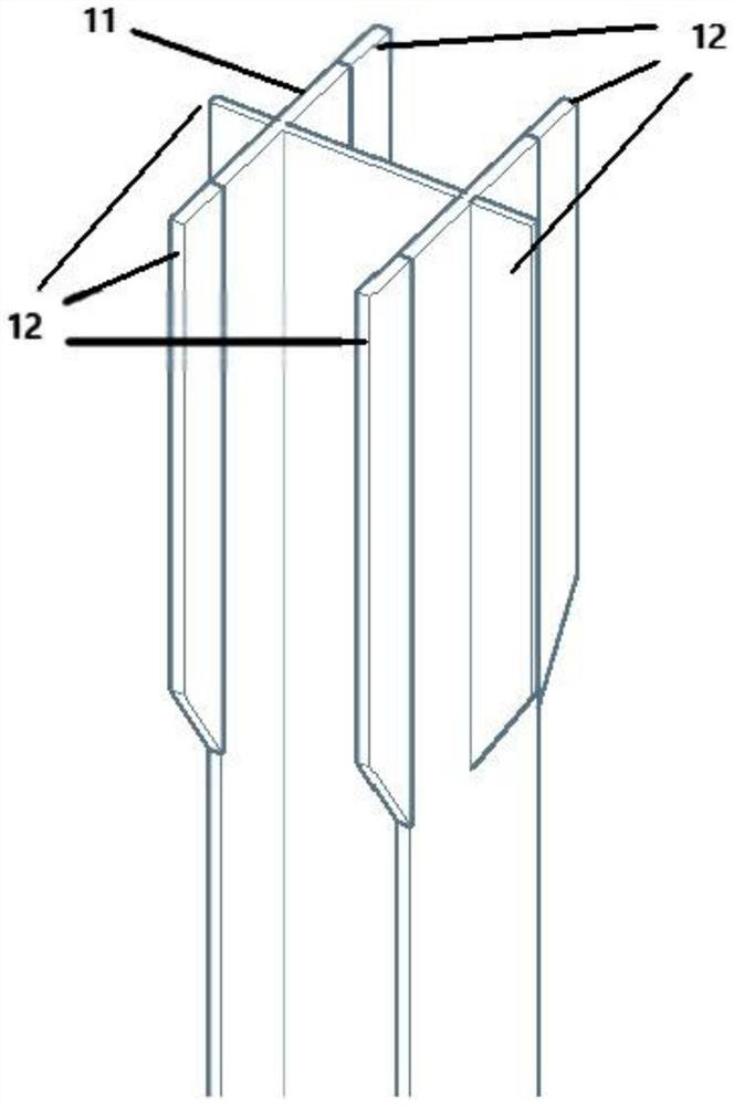
[0024] Such as figure 1 As shown, the present invention is a novel steel-concrete beam-column node with a steel inner sleeve, which mainly consists of a steel-steel concrete upper column with a steel inner sleeve and a steel-steel inner sleeve lower column through its steel inner sleeve 15 for welding connection, and then put on the steel outer sleeve 4 with the corbel, and the two steel outer sleeves 4 with the corbel pass through the high-strength bolt reserved holes 18 of the steel outer sleeve corbel 5 and connect them with high-strength bolts 8 , and then through welding, the steel outer sleeve 4 with the corbel and the steel ring 3 on the column are connected into one body, and finally, the through high-strength bolt 9 is used to pass through the reserved hole 17 of the high-strength bolt to connect the steel outer sleeve with the corbel Sleeve 4, steel inner sleeve 15, column concrete 1, and column H-shaped steel 11 are connected together, so that the components of the ...


PUM


Abstract

The invention discloses an assembly type steel reinforced concrete column-steel reinforced concrete beam joint with an inner steel sleeve and an outer steel sleeve and an installation method. The node is mainly composed of a prefabricated upper steel reinforced concrete column with a steel inner sleeve, a prefabricated lower steel reinforced concrete column with a steel inner sleeve, a steel outer sleeve with a bracket and a prefabricated steel reinforced concrete beam with a stirrup being a square spiral hoop. Section steel of the steel reinforced concrete upper and lower columns with the steel inner sleeves is connected with the inner sleeves in a welded mode through welding rib plates, then longitudinal bars and square spiral stirrups are bound, finally concrete is poured for prefabrication forming, the upper column and the lower column are connected in a welded mode through the steel inner sleeves at the column ends, and the steel outer sleeves with corbels are reinforced through high-strength bolts and welded connection. And then high-strength bolts penetrate through the connecting joints to enable the connecting joints to form a whole, the brackets of the steel outer sleeves are connected with the prefabricated steel reinforced concrete beams through the high-strength bolts, and the beam-column joints are formed at the joints of the brackets and the beams through post-pouring concrete. According to the assembly type steel reinforced concrete column-steel reinforced concrete beam joint with the inner steel sleeve and the outer steel sleeve, the problem of connection of prefabricated steel reinforced concrete is well solved through the joint, good anti-seismic performance is achieved, a large amount of on-site workload can be reduced, and on-site assembly is facilitated.

Description

technical field [0001] The invention relates to an assembled shaped steel concrete column-shaped steel concrete beam joint with inner and outer steel sleeves in the technical field of construction. Background technique [0002] At present, most civil buildings still use reinforced concrete structure, but this kind of structure is heavy, has a long construction period, requires a lot of manpower, and consumes a lot of environmental resources. Steel-reinforced concrete (SRC) refers to a steel-concrete composite structure formed by disposing steel in the original reinforced concrete beams and columns. Compared with traditional reinforced concrete structures, it has strong deformation capacity and good seismic performance, which can reduce the cross-section of beams and columns and increase the use of Space, compared with the steel structure, concrete has both the function of bearing force and protecting the section steel, saves steel, has high structural rigidity, and is easier...

Claims


Application Information

Patent Timeline
Patent Type & Authority Applications(China)
IPC IPC(8): E04B1/58E04C3/36E04C3/293
CPCE04B1/58E04C3/36E04C3/293
Inventor 刘坚戚玉亮陈原任达刘长江唐孟雄曾嵘森彭林苗肖海鹏招渝钟晨浩李高辉周观根刘道志赖帅柏宇翔陈盼盼
Owner GUANGZHOU UNIVERSITY
Why Eureka
Try Eureka