Turbine engine with shock wave attenuation

A turbine engine, engine technology, applied in the direction of engine manufacturing, engine components, engine functions, etc., can solve the problem of engine operation efficiency reduction

Pending Publication Date: 2022-03-11
GENERAL ELECTRIC CO
View PDF0 Cites 0 Cited by
  • Summary
  • Abstract
  • Description
  • Claims
  • Application Information

AI Technical Summary

Problems solved by technology

Shock waves can propagate through the engine and encounter components located within it, creating pressure disturbances that negatively affect the axial flow of the working air, which results in reduced operating efficiency of the engine

Method used


Image

  • Turbine engine with shock wave attenuation
  • Turbine engine with shock wave attenuation
  • Turbine engine with shock wave attenuation

Examples


Embodiment Construction

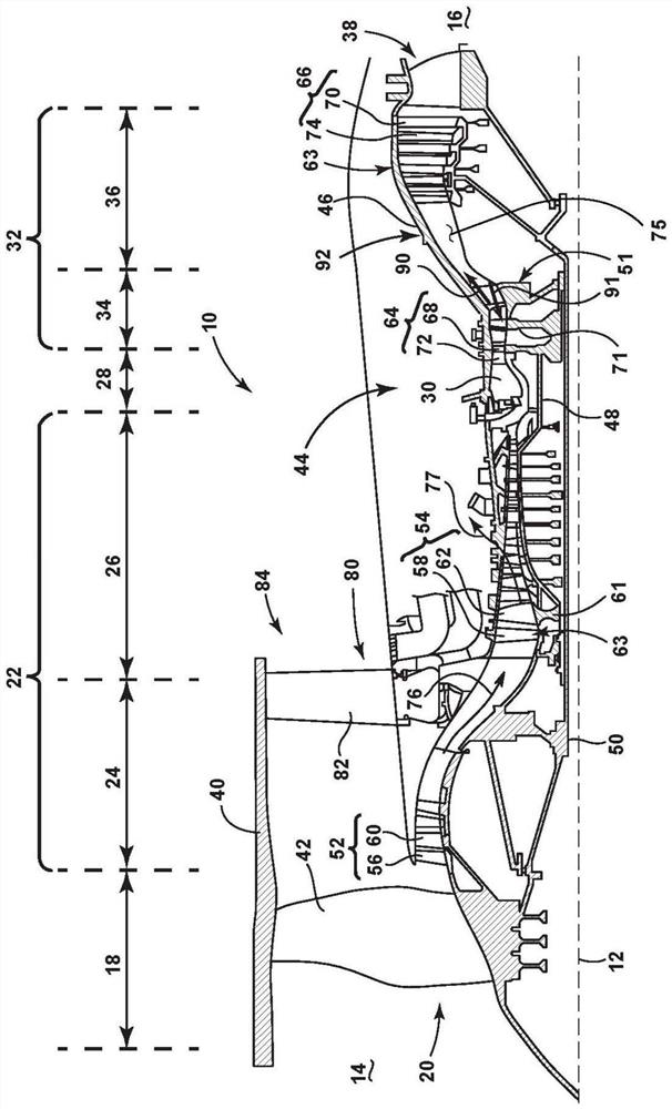
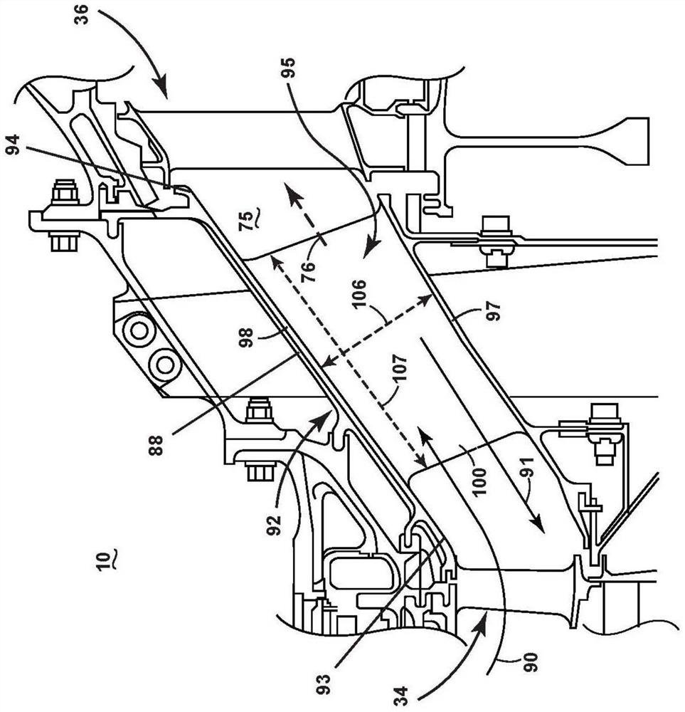
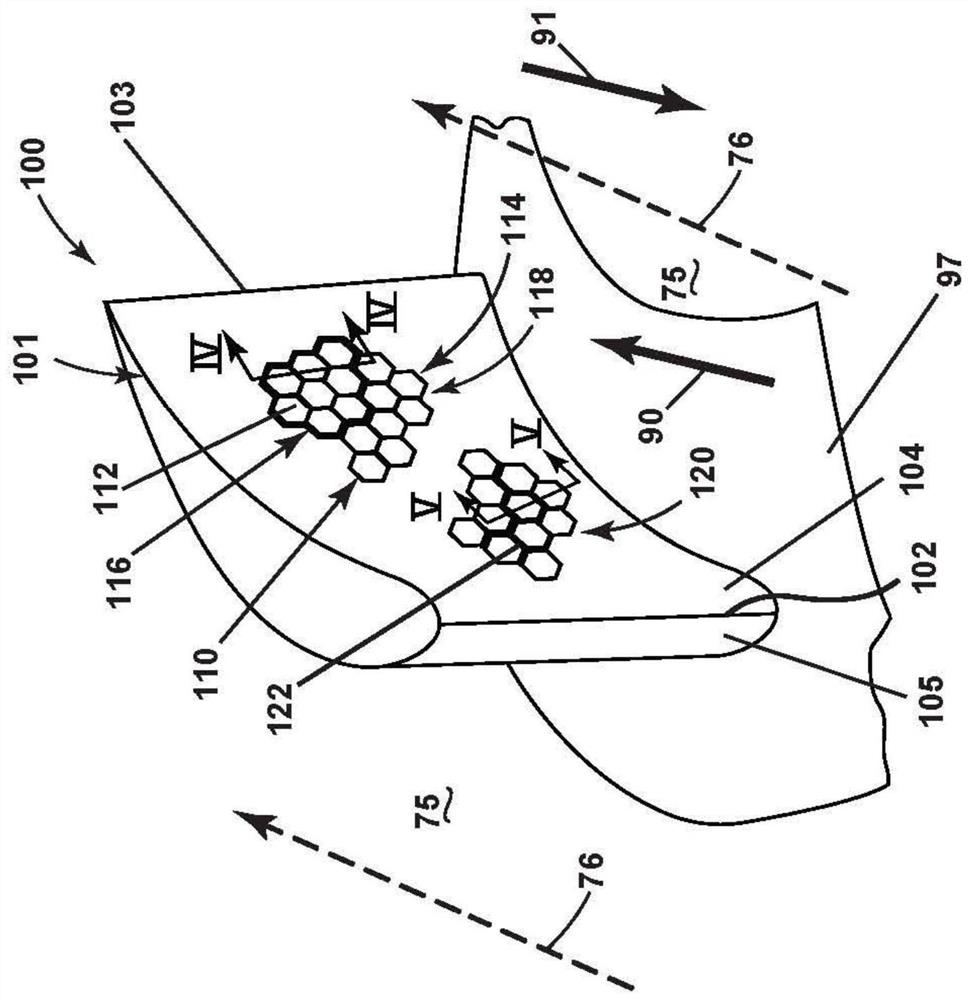
[0025] Recent trends in engine technology, including turbomachinery technology, have produced increases in turbine blade load requirements, including local Mach numbers and subsequent compressible flow phenomena such as shock waves and expansion waves in the working gas stream. This flow characteristic can propagate downstream along the engine flow path, creating pressure losses and reduced efficiency in downstream components. Additionally, some shock waves can reflect off downstream components and create subsequent aerodynamic effects, which can also negatively impact system performance. Additionally, some engine architectures have closely coupled high pressure turbine (HPT) and low pressure turbine (LPT), which can lead to increased aerodynamic or aeroelastic interactions between the HPT and LPT. Aspects of the present disclosure relate to mitigating or attenuating such flow phenomena, including shock waves, through the use of surface features on engine components that may b...


PUM


Abstract

Aspects of the present disclosure generally relate to a turbine engine and a method of operating a turbine engine having an engine core including a compressor, a combustor, and a turbine in an axial flow arrangement such that a working airflow passes from the compressor through the engine core to the turbine to define a flow direction through the engine core. The method includes generating a shock wave in a working gas flow propagating in a flow direction, and at least partially attenuating the shock wave.

Description

[0001] Federally Funded Research [0002] This invention was made with United States Government support. The United States Government may have certain rights in this invention. technical field [0003] The present disclosure relates generally to turbine engines, and more particularly, to turbine engines configured to attenuate shock waves within the engine. Background technique [0004] A turbine engine (specifically a gas or combustion turbine engine) is a rotating engine that extracts energy from process or working air, which flows through the engine through multiple compressor stages, through a combustor, and through multiple turbine stages . The compressor and turbine stages include axially arranged pairs of rotating blades and stationary buckets. [0005] During engine operation, the rotation of the blades induces flow disturbances, such as shock waves, within the working airflow as it advances axially through the engine. Shock waves can propagate through the engine...

Claims


Application Information

Patent Timeline
Patent Type & Authority Applications(China)
IPC IPC(8): F02C3/04F02C7/00F02C7/04F01D25/30F01D25/00
CPCF02C3/04F02C7/00F02C7/04F01D25/30F01D25/00F02C7/24F05D2260/963F05D2250/60Y02T50/60
Inventor 克里斯托弗·赖安·约翰逊保罗·哈德利·维特埃里克·约瑟夫·施罗德卡洛斯·吉尔伯托·费尔南德斯·索托
Owner GENERAL ELECTRIC CO
Why Eureka
Try Eureka