Automatic drainer

An automatic drainage and drainage plug technology, applied in steam traps, mechanical equipment, etc., can solve problems such as inaccurate air pressure control, sealing problems, scale blockage, etc., to eliminate bottom exhaust, reduce errors and malfunctions, works well

Inactive Publication Date: 2022-03-11
王晓永
View PDF0 Cites 0 Cited by
  • Summary
  • Abstract
  • Description
  • Claims
  • Application Information

AI Technical Summary

Problems solved by technology

[0003] When the automatic drainer is in use, the float inside the cup is affected by the buoyancy. When there is less water in the cup, the height of the float is lower, so the piston inside it compresses the spring under the action of air pressure so that it will drain water. The hole is blocked, which can ensure that the water inside the water cup will not be discharged and can isolate the inside of the water cup from the outside air. However, after the water accumulates to a certain height, it will drive the lever on the top to open the valve so that the air pressure enters the inside of the valve body. Because the piston part designed inside the valve body has a large air pressure area, this makes the piston slide down to open the drain hole to achieve drainage, but after draining, the internal air pressure will be discharged from the bottom drain hole. This design has a tightness. Problems lead to inaccurate air pressure control inside the valve body. At the same time, air pressure is used to control the piston to ensure that a stable air pressure must be maintained. A certain change or instability of the air pressure at the bottom of the piston will cause its malfunction, and the existing The bottom of the drainage control structure will accumulate, so that the internal water cannot be completely drained under the condition of drainage, so that scale will form at the bottom of the water cup for a long time and cause blockage

Method used


Image

  • Automatic drainer
  • Automatic drainer
  • Automatic drainer

Examples


Embodiment Construction

[0017] The following will clearly and completely describe the technical solutions in the embodiments of the present invention with reference to the accompanying drawings in the embodiments of the present invention. Obviously, the described embodiments are only some, not all, embodiments of the present invention. Based on the embodiments of the present invention, all other embodiments obtained by persons of ordinary skill in the art without making creative efforts belong to the protection scope of the present invention.

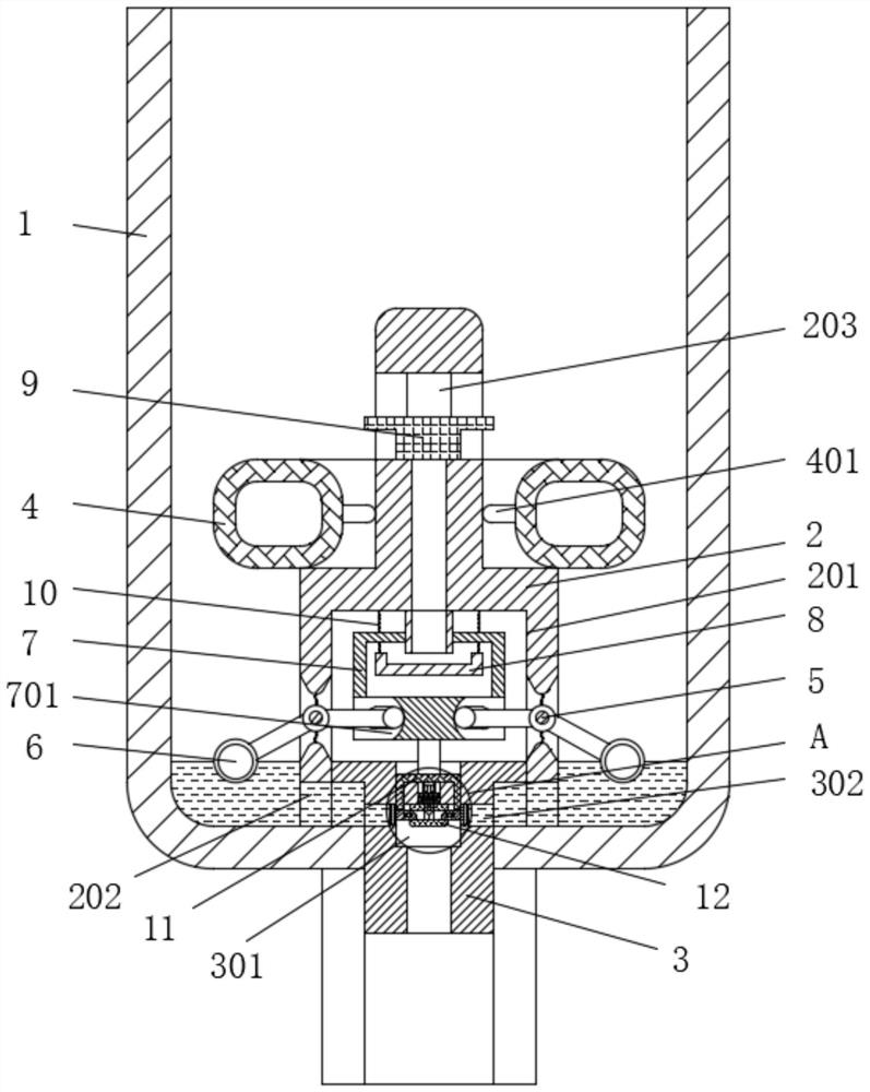
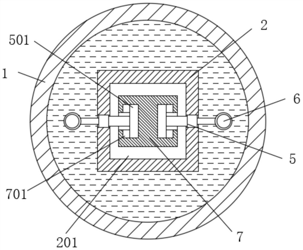
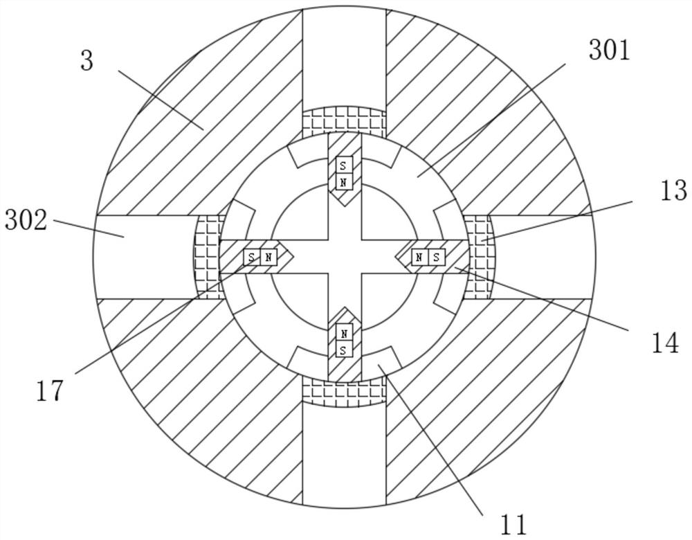
[0018] Please refer to the attached figure 1 , attached figure 2 , attached Figure 4 , attached Figure 5 , an automatic drainer, comprising a water cup 1, a float bracket 2 is fixedly installed in the middle of the inner bottom surface of the water cup 1, and a movable cavity 201 is opened inside the float bracket 2, and a fixed column 3 is fixedly sleeved on the bottom of the movable cavity 201, and the float bracket The top outer ring of 2 is movably s...


PUM


Abstract

The invention relates to the technical field of drainage equipment, and discloses an automatic drainer which is characterized in that the bottom of a movable cavity is fixedly sleeved with a fixed column, a movable block is movably mounted in the middle of the movable cavity, and rotating rods with one ends sleeved with the movable block through connecting rods are symmetrically and movably mounted on the inner walls of the two sides of a floater support; the bottom of the movable block is fixedly connected with a limiting block movably connected with the interior of the sleeve hole in a sleeved mode, the movable block is in a frame shape, a fixed frame is fixedly installed at the position, located in the middle of the movable block, of the interior of the movable cavity, and the end, located in the movable cavity, of the rotating rod is fixedly connected with a sliding rod through a connecting rod; a rotating rod floating ball is arranged in the water cup to be matched with a movable block for control, and a fixed column and a limiting block structure are arranged to be matched with each other to control drainage, so that the air tightness and the automatic drainage effect of the automatic drainer are improved.

Description

technical field [0001] The invention relates to the technical field of drainage equipment, in particular to an automatic drainer. Background technique [0002] The automatic drain is used to automatically remove the condensed water in the lower part of the pipeline, the oil-water separator, the bottom of the gas tank and various filters, etc. It is generally installed in places where it is inconvenient to manually drain sewage, such as high places, low places, and narrow places. And it can prevent the compressed air from being re-contaminated by condensed water due to the manual drainage being forgotten. Because its internal structure can realize automatic drainage after the accumulated water reaches a certain height, although it is widely used, it still has certain shortcomings: [0003] When the automatic drainer is in use, the float inside the cup is affected by the buoyancy. When there is less water in the cup, the height of the float is lower, so the piston inside it co...

Claims


Application Information

Patent Timeline
IPC IPC(8): F16T1/26F16T1/42F16T1/38
CPCF16T1/26F16T1/42F16T1/383
Inventor 王晓永
Owner 王晓永
Why Eureka
Try Eureka