

Defect detection equipment and method
A defect detection and equipment technology, applied in the direction of measuring device, optical instrument testing, machine/structural component testing, etc., can solve the problems of low detection efficiency and low detection accuracy, achieve dynamic identification, improve detection accuracy and detection efficiency Effect
Pending Publication Date: 2022-03-11
ZHONGTIAN TECH ADVANCED MATERIALS CO LTD
View PDF6 Cites 0 Cited by
- Summary
- Abstract
- Description
- Claims
- Application Information
AI Technical Summary
Problems solved by technology
[0004] However, manual detection of defects in optical fiber preforms not only has low detection accuracy, but also low detection efficiency
Method used
View moreImage
Smart ImageViewing Examples

Examples
Embodiment
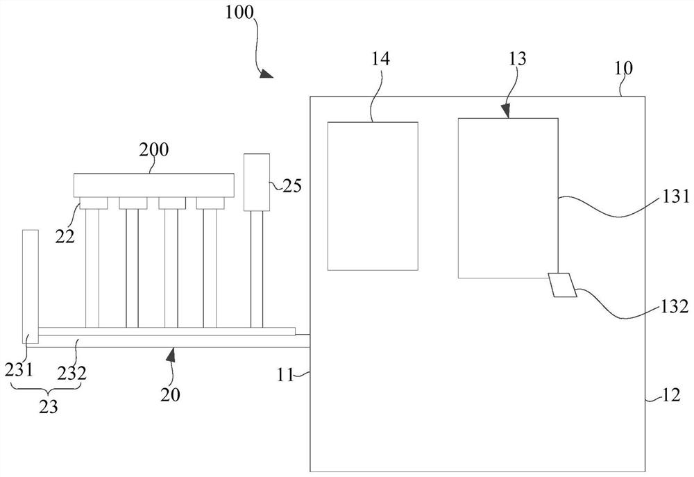
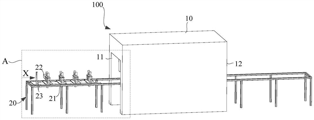
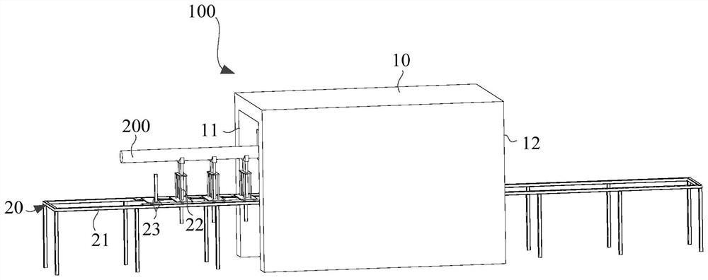
[0068] figure 1 is a schematic diagram of a defect detection device provided by an embodiment of the present invention, figure 2 It is a structural schematic diagram of a defect detection device provided by an embodiment of the present invention under a first viewing angle, image 3 It is a schematic diagram of the assembly of a preform on the defect detection equipment provided by the embodiment of the present invention. in, figure 1 It is a schematic diagram of the structure of the defect detection equipment.
Login to View More PUM
 Abstract
The invention provides defect detection equipment and method, the detection equipment comprises a detection mechanism and a detection table, the detection mechanism is provided with a detection unit, and the detection mechanism is provided with an inlet and an outlet for a preform to enter and exit at two opposite ends of the detection unit. The detection table comprises a transfer unit, a plurality of supporting assemblies for supporting the preform and a detection line arranged in the detection mechanism in a penetrating manner; the detection line is positioned below the detection unit. The supporting assembly is driven by the transferring unit to move relative to the detection line in the extending direction of the detection line and drives the preform to move relative to the detection unit. According to the defect detection equipment provided by the invention, the detection precision and the detection efficiency can be improved.
Description
technical field [0001] The invention relates to the technical field of optical fiber defect detection, in particular to a defect detection device and method. Background technique [0002] With the development of the communication industry and the rise of the fifth generation mobile communication technology (5th Generation Mobile Communication Technology, 5G technology), the application of optical fiber is becoming more and more extensive. [0003] Optical fiber preforms are used as raw materials for optical fiber production, and their mainstream processes mainly include out-of-tube vapor deposition (OVD), vapor axial deposition (VAD), improved in-tube chemical vapor deposition (MCVD), and plasma in-tube chemical vapor deposition. method (PCVD). The above four mainstream processes can be combined to synthesize optical fiber preforms according to the "two-step method". Limited by the existing technology level, it is easy to generate bubbles or opaque impurities in the core l...
Claims
Login to View More Application Information
Patent Timeline
 Patent Type & AuthorityApplications(China)
IPC IPC(8): G01N21/952G01M11/00
CPCG01N21/952G01M11/00
Inventor徐金田赵海伦施仁杰沈一春
OwnerZHONGTIAN TECH ADVANCED MATERIALS CO LTD