
Lens module and head-mounted display device

A module and lens technology, which is applied in the field of head-mounted display devices, can solve the problems of large lens volume and high refractive index requirements of the lens, and achieve the effect of improving the field of view

Pending Publication Date: 2022-03-11
GOERTEK OPTICAL TECH CO LTD
View PDF3 Cites 0 Cited by
  • Summary
  • Abstract
  • Description
  • Claims
  • Application Information

AI Technical Summary

Problems solved by technology

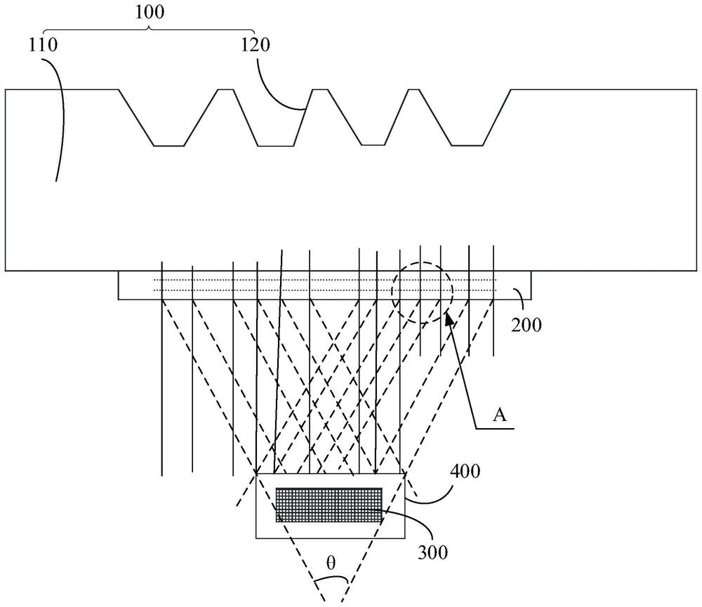
[0003] The angle of view is usually the angle between the edge of the virtual image and the edge of the orbit. In order to increase the angle of view, the traditional method can usually increase the area of ​​the lens, or reduce the orbit, or increase the lens substrate. Refractive index, etc., so that the volume of the entire lens is larger or the requirements for the refractive index of the lens are higher

Method used


Image

  • Lens module and head-mounted display device
  • Lens module and head-mounted display device
  • Lens module and head-mounted display device

Examples


Embodiment Construction

[0031] The following will clearly and completely describe the technical solutions in the embodiments of the present invention with reference to the accompanying drawings in the embodiments of the present invention. Obviously, the described embodiments are only part of the embodiments of the present invention, not all of them. Based on the embodiments of the present invention, all other embodiments obtained by persons of ordinary skill in the art without creative efforts fall within the protection scope of the present invention.

[0032] It should be noted that if there is a directional indication (such as up, down, left, right, front, back...) in the embodiment of the present invention, the directional indication is only used to explain the position in a certain posture (as shown in the accompanying drawing). If the specific posture changes, the directional indication will also change accordingly.

[0033] In addition, if there are descriptions involving "first", "second" and ...


PUM


Abstract

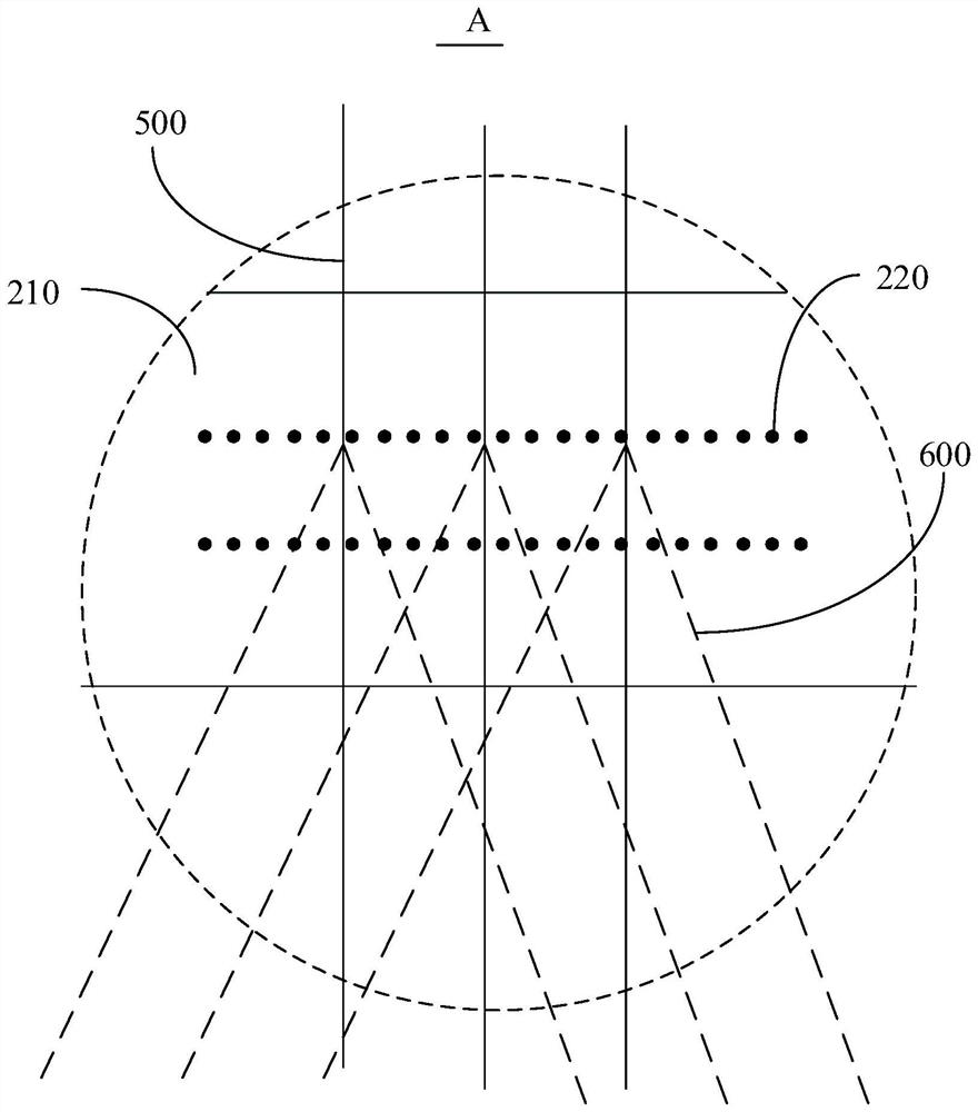
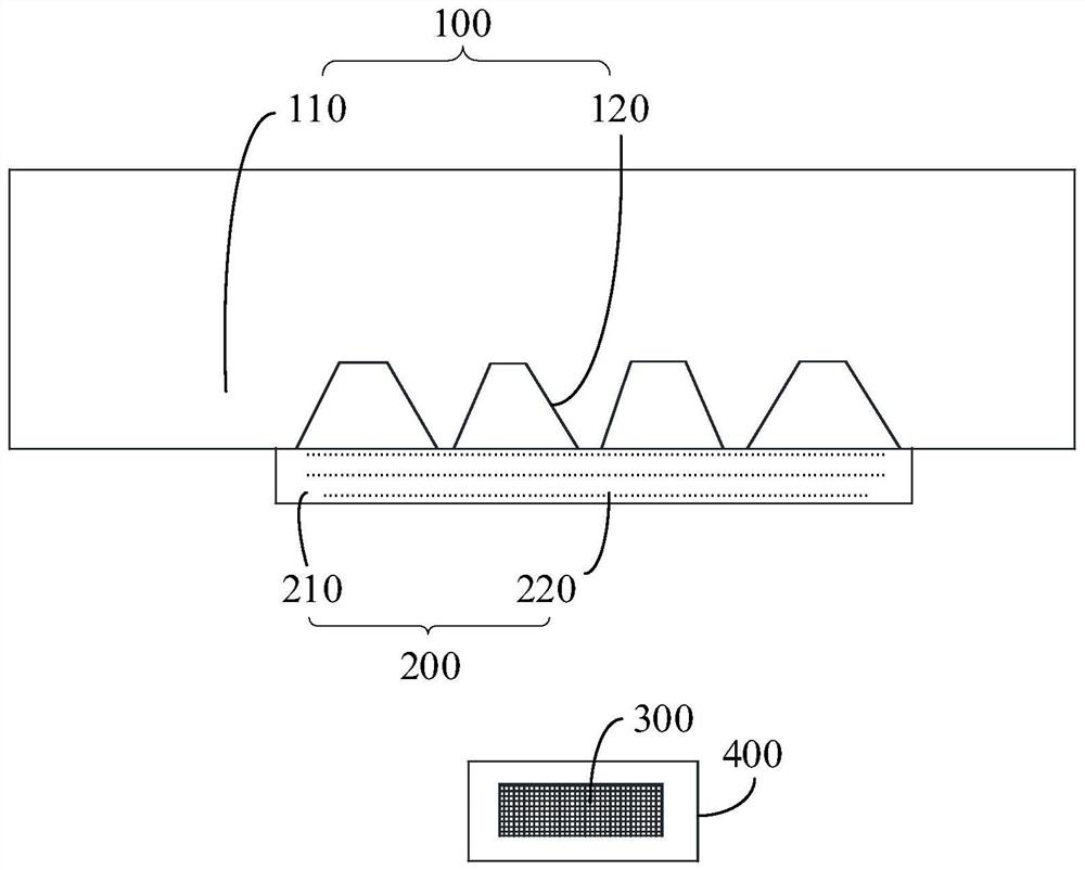
The invention discloses a lens module and a head-mounted display device. The lens module comprises an optical substrate and a quantum layer, the optical substrate comprises a light inlet part and a light outlet part, and light is emitted to the optical substrate through the light inlet part and is emitted to human eyes through the light outlet part; the light emitting part is partially provided with an emphasis display area, and the quantum layer is arranged on the optical substrate and located on the side, facing the human eyes, of the emphasis display area of the light emitting part. According to the technical scheme, the quantum layer is arranged on the optical substrate and located on the side, facing the human eyes, of the emphasis display area of the light emitting part of the optical substrate, the light rays emitted by the light emitting part can penetrate through the quantum layer and then enter the human eyes, and when the light rays penetrate through the quantum layer, quantum dots in the quantum layer can be excited to emit light; and the angle of the light emitted by the quantum dots is not restrained, so that the light emitted by the quantum dots can compensate for a smaller light angle emitted from the emphasis display area of the light emitting part of the optical substrate, and the field angle is further improved.

Description

technical field [0001] The invention relates to the technical field of display devices, in particular to a lens module and a head-mounted display device using the lens module. Background technique [0002] For an augmented reality head-mounted display device, its field of view and eye movement are very important parameters. The field of view directly determines the frame size of the virtual image that the user can see. The larger the field of view, the larger the area of ​​the virtual image displayed, and the better the immersive experience. The moving eye socket directly affects the range in which the user can see the virtual image, and it determines the flexibility of wearing the head-mounted display device. If the moving eye socket is too small, the user will see incomplete virtual content when the device is moved a little. [0003] The field of view is usually the angle between the edge of the virtual image and the orbital edge. In order to increase the field of view, t...

Claims


Application Information

Patent Timeline
IPC IPC(8): G02B27/01
CPCG02B27/0172
Inventor 朱瑞李德华惠晓辉
Owner GOERTEK OPTICAL TECH CO LTD
Learn More