Horizontal on-load capacity-regulating tap switch

A tap changer and capacity adjustment technology, applied in electrical switches, high-voltage/high-current switches, high-voltage air circuit breakers, etc., can solve the problems of increasing the volume and cost of the transformer, complicated internal wiring of the switch, and reducing the insulation performance of the switch, etc. To achieve the effect of simple and reliable driving mode, simple internal wiring, and saving expensive costs

Pending Publication Date: 2022-03-11
GUANGDONG CHAMPON ELECTRIC CO LTD
View PDF0 Cites 0 Cited by
  • Summary
  • Abstract
  • Description
  • Claims
  • Application Information

AI Technical Summary

Problems solved by technology

[0002] At present, there are few horizontal on-load capacity-regulating tap-changers in the market. The traditional cylindrical on-load capacity-regulating tap-changer device is installed on the side of the transformer, and its volume is relatively large, which greatly increases the volume and capacity of the transformer. Cost, and the internal wiring is complicated, assembly is difficult, and it is very inconvenient to use
The new horizontal on-load capacity regulating tap-changer device that has appeared on the market in the past one or two years adopts the traditional mechanical tapping structure for closing and disconnecting the high-voltage side dynamic and static contacts inside the switch. During the capacitance process, the high-voltage side contacts of the switch will generate arcs during the closing and opening process, which will seriously affect the life of the contacts and pollute the insulating oil inside the switch, reducing the insulation performance of the switch, which is not good for the life of the switch. The complex problem of wiring can not be solved

Method used


Image

  • Horizontal on-load capacity-regulating tap switch
  • Horizontal on-load capacity-regulating tap switch
  • Horizontal on-load capacity-regulating tap switch

Examples


Embodiment Construction

[0031] In order to make the object, technical solution and advantages of the present invention clearer, the present invention will be further described in detail below in conjunction with the accompanying drawings. It is only stated here that the words for directions such as up, down, left, right, front, back, inside, and outside that appear or will appear in the text of the present invention are only based on the accompanying drawings of the present invention, and are not specific to the present invention. limited.

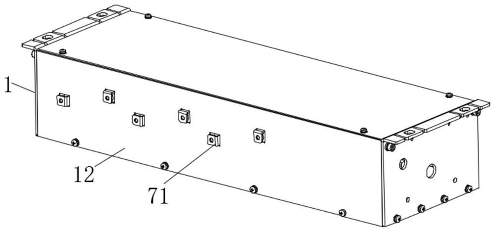
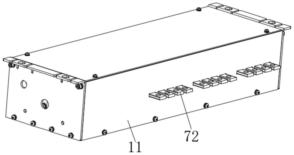
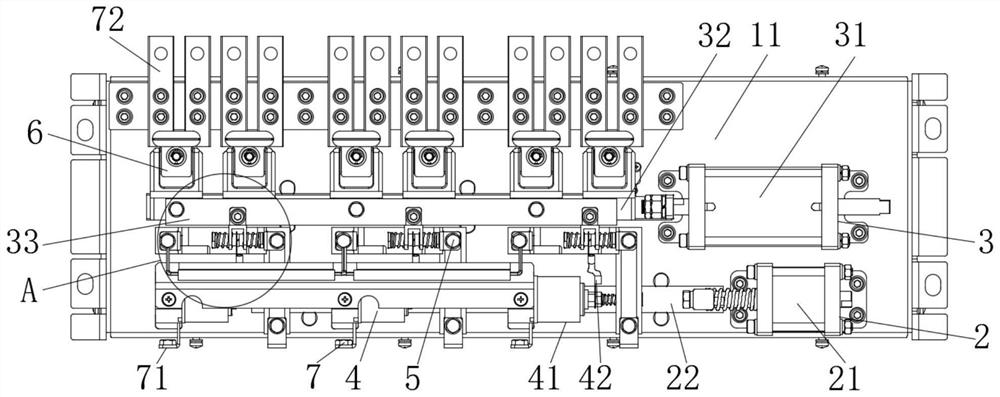
[0032] see figure 1 , figure 2 with image 3 , the embodiment of the present invention discloses a horizontal on-load capacity regulating tap-changer, which is used to realize the capacity exchange of the transformer, including a housing 1 and a first driving assembly 2 fixed in the housing 1, a second driving assembly Component 3, vacuum arc extinguishing component 4, double-station switching component 5, low-voltage contact component 6 and wiring component ...


PUM


Abstract

The invention discloses a horizontal on-load capacity-regulating tap switch which comprises a shell, a vacuum arc extinguishing assembly, a double-station switching assembly, a low-voltage contact assembly and a wiring assembly, the vacuum arc extinguishing assembly, the double-station switching assembly, the low-voltage contact assembly and the wiring assembly are fixed in the shell, the shell comprises an insulating substrate, and the wiring assembly is provided with a plurality of first wiring pieces. The wiring assembly is provided with a plurality of first wiring pieces, the first wiring pieces are in lap joint with taps on the high-voltage side of the transformer, the wiring assembly is further provided with a plurality of second wiring pieces, the second wiring pieces are in lap joint with taps on the low-voltage side of the transformer, and the double-station switching assembly comprises a movable contact set and a static contact set. The vacuum arc extinguishing assembly can disconnect the electric connection with the movable contact group and the static contact group under the linear driving of the first driving assembly and carry out vacuum arc extinguishing. According to the invention, transformer oil is not polluted in the capacity exchange process, the service life of the moving contact group is prolonged, the layout is compact, the size is small, and the switch cost and the transformer cost can be effectively reduced.

Description

technical field [0001] The invention relates to the technical field of electric equipment, in particular to a horizontal on-load capacity regulating tap changer. Background technique [0002] At present, there are few horizontal on-load capacity-regulating tap-changers in the market. The traditional cylindrical on-load capacity-regulating tap-changer device is installed on the side of the transformer, and its volume is relatively large, which greatly increases the volume and capacity of the transformer. Cost, and the internal wiring is complicated, the assembly is difficult, and it is very inconvenient to use. The new horizontal on-load capacity regulating tap-changer device that has appeared on the market in the past one or two years adopts the traditional mechanical tapping structure for closing and disconnecting the high-voltage side dynamic and static contacts inside the switch. During the capacitance process, the high-voltage side contacts of the switch will generate a...

Claims


Application Information

Patent Timeline
Patent Type & Authority Applications(China)
IPC IPC(8): H01H33/664H01H3/32H01F21/00
CPCH01H33/664H01H3/32H01F21/00
Inventor 董良群吴卫华
Owner GUANGDONG CHAMPON ELECTRIC CO LTD
Why Eureka
Try Eureka