Wire harness anti-disconnection connection structure for high-frequency vibration structure of mechanical equipment
A high-frequency vibration and mechanical equipment technology, applied in the direction of connection, parts of the connection device, coupling device, etc., can solve problems such as loose connection of the equipment line body, affecting the normal operation of the equipment, and poor contact at the connection end, so as to avoid Reverse detachment, avoiding loosening, and improving stability
- Summary
- Abstract
- Description
- Claims
- Application Information
AI Technical Summary
Problems solved by technology
Method used
Image
Examples
Embodiment 1
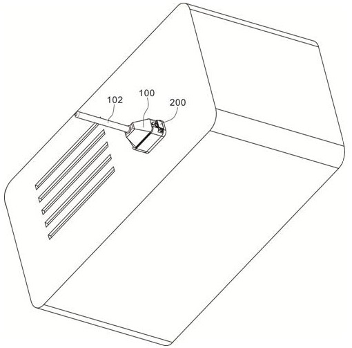
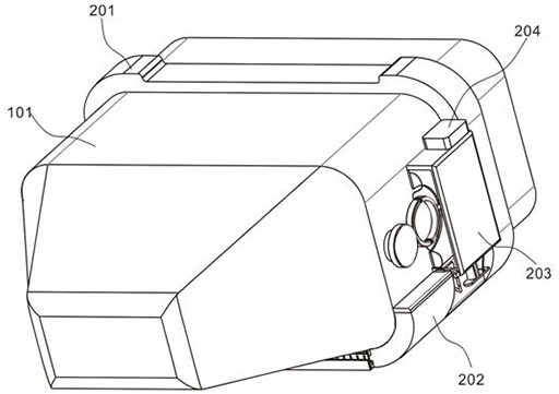
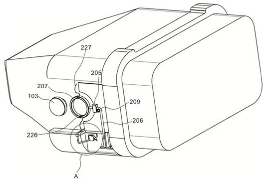
[0020] Example 1: Please refer to figure 1 and figure 2 , the present invention provides a wire harness anti-disconnection connection structure for a high-frequency vibration structure of mechanical equipment, including a wire harness unit 100, including a power head 101, the power head 101 is connected to the wire harness body 102, and the power head 101 is symmetrically provided with a buckle plate on the surface 103; the anti-dropping unit 200 includes a device body, a rectangular sleeve plate 201 is fixedly arranged at the periphery of the power port on the surface of the device body, the bottom of the rectangular sleeve plate 201 is fixedly connected to the concave support plate 202, and the surface of the rectangular sleeve plate 201 is fixedly connected with a U-shaped shell 203, a controller 204 is provided on the top of the rectangular sleeve plate 201.
[0021] see Figure 5 and Image 6 , the left side and bottom surface of the U-shaped shell 203 are both open-s...
Embodiment 2
[0024] Example 2: Please refer to image 3 and Figure 4 The inner cavity of the U-shaped shell 203 is provided with a mounting substrate 216, the mounting substrate 216 is located on the left side of the initial position of the gravity block 210, and a folding tube 217 is fixed on the surface of the mounting substrate 216, and the bottom end of the folding tube 217 is movably inserted with a piston When the rod 218, the gravity block 210 swings to the left and impacts, it contacts the piston rod 218 and pushes the air in the folded tube 217 intermittently. There are rubber air valves 219.
[0025] The top end of the folded tube 217 is movably inserted with an L-shaped strut 220, and the end of the folded tube 217 is provided with a one-way air valve (not numbered in the figure), and the end of the L-shaped strut 220 is movably inserted into the curved conduit 221 Inside, the end of the curved conduit 221 is fixedly arranged through the U-shaped housing 203, and the top of t...
PUM
 Abstract
Description
Claims
Application Information
 - R&D
- Intellectual Property
- Life Sciences
- Materials
- Tech Scout
- Unparalleled Data Quality
- Higher Quality Content
- 60% Fewer Hallucinations
Browse by: Latest US Patents, China's latest patents, Technical Efficacy Thesaurus, Application Domain, Technology Topic, Popular Technical Reports.
© 2025 PatSnap. All rights reserved.Legal|Privacy policy|Modern Slavery Act Transparency Statement|Sitemap|About US| Contact US: help@patsnap.com


