Method and conductor structure for producing electrical winding of electromagnetic induction device

A technology of electromagnetic induction and conductor structure, applied in the direction of transformer/inductor coil/winding/connection, transformer/inductor components, coil manufacturing, etc., can solve the problems of dangerous unbalanced state and collapse of winding structure

Pending Publication Date: 2022-03-11
HITACHI ENERGY SWITZERLAND AG
View PDF2 Cites 0 Cited by
  • Summary
  • Abstract
  • Description
  • Claims
  • Application Information

AI Technical Summary

Problems solved by technology

[0010] The above-mentioned technical problems may lead to a dangerous unbalanced state of the entire winding structure, which may lead to its collapse under certa...

Method used


Image

  • Method and conductor structure for producing electrical winding of electromagnetic induction device
  • Method and conductor structure for producing electrical winding of electromagnetic induction device
  • Method and conductor structure for producing electrical winding of electromagnetic induction device

Examples


Embodiment Construction

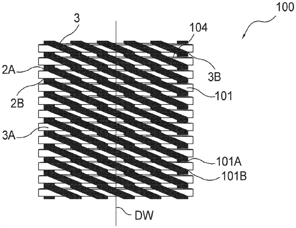
[0040] With reference to the above figures, the present invention relates to a method for manufacturing an electrical winding 100 for an electromagnetic induction device (not shown) for power transmission and distribution networks.

[0041] Such electromagnetic induction devices may be power transformers for power transmission and distribution networks, such as power transformers or distribution transformers.

[0042] The manufacturing method according to the invention comprises the steps of providing a conductor structure 1 for forming an electrical winding 100 ( image 3 , Figure 4 ).

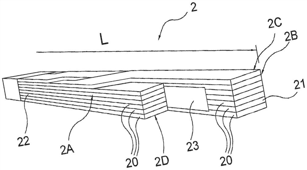
[0043] The conductor structure 1 comprises a conductor element 2 ( figure 1 ).

[0044] Preferably, the conductor element 2 is shaped to comprise the shape of an elongated parallelepiped made of electrically conductive material.

[0045] Preferably, the conductor element 2 has a suitable cross-section (eg a rectangular or square cross-section) of the opposing first and second sides 2A, 2...


PUM

PropertyMeasurementUnit
Thicknessaaaaaaaaaa

Abstract

A method for producing an electrical winding of an electromagnetic induction device, comprising the following steps: providing a conductor structure (1) comprising a conductor element (2) extending longitudinally in a main direction of extension (L) and one or more spacer strips (3) made of an electrically insulating material surrounding the conductor element in the main direction of extension (L), each spacing strip has spacing portions (3A, 3B) at respective sides (2A, 2B) of the conductor element, the spacing portions (3A, 3B) being spaced apart from each other along the sides (2A, 2B) of the conductor element; forming an electrical winding (100) by means of the conductor structure, the electrical winding extending axially in a winding direction (DW) and having a plurality of turns (101) arranged around the winding direction. Each turn (101) of the electrical winding (100) is formed by a respective longitudinal portion (2E, 2F) of the conductor element (2). The spacer portions (3A, 3B) of each spacer strip (3) are inserted between adjacent turns of the electrical winding (100) at opposite sides (101A, 101B) of the turns (101). The spacing portions (3A, 3B) are each placed spaced apart from one another to define an empty space (3C) for forming a radial channel (104) of the electrical winding (100), where the radial channel (104) is configured for passage of an electrically insulating medium.

Description

technical field [0001] The present invention relates to the field of electromagnetic induction devices, such as power transformers, for use in power transmission and distribution networks. [0002] More specifically, the invention relates to a method and conductor structure for the manufacture of electrical windings of electromagnetic induction devices. Background technique [0003] The electrical windings of electromagnetic induction devices can be manufactured on an industrial level according to various methods. [0004] One widely used method involves winding a conductor around a winding direction such that an electrical winding has a plurality of adjacent turns arranged around said winding direction. [0005] As is known, generally, electrical windings for electromagnetic induction devices have axial and radial channels to ensure the passage of an electrically insulating medium, such as an insulating fluid or a solid casting resin, between the turns. [0006] Tradition...

Claims


Application Information

Patent Timeline
IPC IPC(8): H01F41/06H01F27/32H01F27/28
CPCH01F41/06H01F27/323H01F27/28H01F27/2823H01F2027/2838H01F27/322H01F41/122H01F5/06H01F27/32H01F41/12
Inventor G·布斯特罗P·帕瓦内洛M·卡米诺托
Owner HITACHI ENERGY SWITZERLAND AG
Why Eureka
Try Eureka