
Adjustable LED (light emitting diode) illuminating lamp

An LED lighting lamp, an adjustable technology, is applied in lighting devices, lighting and heating equipment, components of lighting devices, etc. The effect of simplifying, improving adjustment accuracy, and improving structural balance

Inactive Publication Date: 2012-10-03
盘锦中跃光电科技有限公司
View PDF6 Cites 0 Cited by
  • Summary
  • Abstract
  • Description
  • Claims
  • Application Information

AI Technical Summary

Problems solved by technology

For this kind of LED, there is a problem that because the light source is a plane light source, it is impossible to use the traditional solution to adjust the LED lighting range by adjusting the distance between the reflector and the light source. LEDs, usually fixed structures, cannot adjust the lighting range
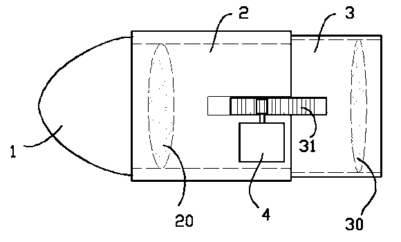
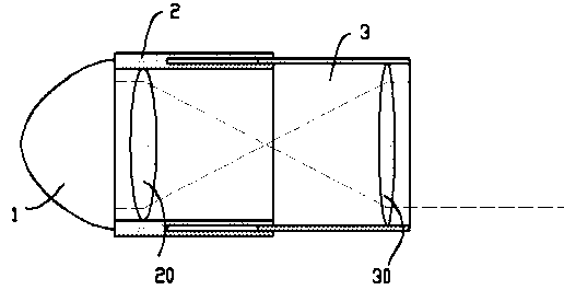
[0005] For the above situation, the applicant has proposed a lens group controllable LED in patent 20121051719.6, such as figure 1 , figure 2 As shown, it includes a lamp cap 1 capable of producing parallel light, a fixed sleeve 2, and an adjusting sleeve 3. The adjusting sleeve 3 can slide axially along the fixed sleeve 2. The fixed sleeve 2 and the adjusting sleeve 3 are respectively fixed with a fixed convex lens 20 and an adjusting sleeve. The convex lens 30 can adjust the lighting range flexibly and accurately by adjusting the distance between the fixed convex lens 20 and the adjustable convex lens 30 by moving the adjusting sleeve 3. However, in this patent, the driving mechanism for controlling the adjusting sleeve 3 is fixed on the adjusting sleeve 3 on the rack 31 and a stepper motor engaged with the rack, which not only makes the structure of the entire LED cumbersome, but also lower assembly and manufacturing efficiency

Method used


Image

  • Adjustable LED (light emitting diode) illuminating lamp
  • Adjustable LED (light emitting diode) illuminating lamp
  • Adjustable LED (light emitting diode) illuminating lamp

Examples


Embodiment Construction

[0020] Below in conjunction with accompanying drawing and embodiment the present invention is further described:

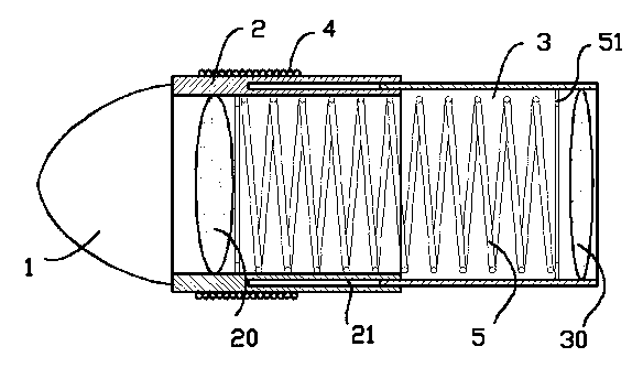
[0021] exist image 3 In the shown embodiment, the adjustable LED lighting lamp includes a lamp head 1 capable of producing parallel light; a controllable optical assembly is provided in front of the lamp head 1, and the assembly includes a fixing sleeve 2 fixed to the lamp head 1, a The adjusting sleeve 3 of the fixed sleeve 2 axially slides, the two cooperate through the chute 21 opened on the end surface of the ring fixed sleeve 2, and the adjusting sleeve 3 slides in the chute; the fixed sleeve 2 and the adjusting sleeve 3 are respectively fixed There are a fixed convex lens 20 and an adjustable convex lens 30; the fixed convex lens 20 can converge the parallel light generated by the lamp head 1 at the focal point and shoot it to the surface of the adjustable convex lens 30, and its optical path is as follows figure 2 Shown by the dotted line in the middle; ...


PUM


Abstract

The invention provides an adjustable LED (light emitting diode) illuminating lamp which comprises a lamp head capable of generating parallel light; a controllable optical component is arranged at the front of the lamp head, the component comprises a fixed cover fixed with the lamp head and an adjustable cover capable of axially sliding along with the fixed cover; the fixed cover and the adjustable cover are internally fixed with a fixed convex lens and an adjustable convex lens respectively; the fixed convex lens can converge the parallel light generated by the lamp head at a focal point and radiate to the surface of the adjustable convex lens; the fixed cover and the adjustable cover are made from silicon steel; the end of the fixed cover, which is close to the lamp head, is covered with a magnet exciting coil, the fixed cover and the adjustable cover are internally provided with a pressure spring respectively, and two ends of the pressure spring are respectively and relatively fixed with the outer edge of the fixed convex lens and the outer edge of the adjustable convex lens; the magnet exciting coil is connected with an LED (light emitting diode) controller; and the LED controller comprises a voltage reducing module, a rectifying module, a constant-voltage and voltage-current module and a magnet exciting coil current control module. The adjustable LED illuminating lamp not only can flexibly and exactly adjust the illuminating range, but also is simple in structure, and convenient to manufacture.

Description

[0001] technical field [0002] The invention relates to the field of lighting devices, in particular to an LED lighting lamp capable of adjusting the lighting range. [0003] Background technique [0004] Due to low energy consumption and high brightness, LED lighting has been rapidly developed in recent years and has been gradually popularized in various lighting places. The light-emitting element of the LED is a light-emitting diode. Because the brightness of a single light-emitting diode is relatively limited, the light-emitting part of the LED lighting device is usually composed of a large number of light-emitting diode arrays, and the planar array is the most commonly used. A large number of light-emitting diodes are arrayed in front of the lamp head. In a large number of reflective pits evenly distributed on the panel, the reflective pits can reflect the light of the LED into parallel light and emit it outward. For this kind of LED, there is a problem that because t...

Claims


Application Information

Patent Timeline
Patent Type & Authority Applications(China)
IPC IPC(8): F21S2/00F21V14/06F21Y101/02F21K9/235F21K9/238F21Y115/10
Inventor 马根昌
Owner 盘锦中跃光电科技有限公司
Learn More