Substation inspection robot system and obstacle avoidance method thereof

A technology for inspecting robots and substations, which is applied in manipulators, program-controlled manipulators, manufacturing tools, etc., and can solve problems such as lack of detection and normal connection.

Pending Publication Date: 2022-03-15
信通院车联网创新中心(成都)有限公司
View PDF1 Cites 0 Cited by
  • Summary
  • Abstract
  • Description
  • Claims
  • Application Information

AI Technical Summary

Problems solved by technology

[0005] Since the power equipment installed in the substation often bears relatively large power, it will inevitably generate a corresponding electric field or magnetic field in its surrounding space during normal operation, and the greater the current flowing on the power equipment, the closer it is to the equipment , the stronger the electric field or magnetic field, so for the intelligent robot provided in the above patent application documents, when it is applied to a specific substation, if the robot itself is too close to the power equipment, not only the communication between it and the host computer will be affected. The electric field or magnetic field interference cannot be connected normally, and its internal electronic devices will also be affected by the electric field or magnetic field and cannot work normally. However, according to the above-mentioned patent application documents, its detection unit only includes an infrared detection unit and an ultraviolet detection unit. The ability to avoid interference by electric or magnetic fields and further avoid electric or magnetic fields

Method used


Image

  • Substation inspection robot system and obstacle avoidance method thereof

Examples


Embodiment Construction

[0042] In order to make the object, technical solution and advantages of the present invention clearer, the present invention will be further described in detail below in conjunction with the accompanying drawings and embodiments. It should be understood that the specific embodiments described here are only used to explain the present invention, not to limit the present invention.

[0043] To achieve the above object, the technical scheme of the present invention is as follows:

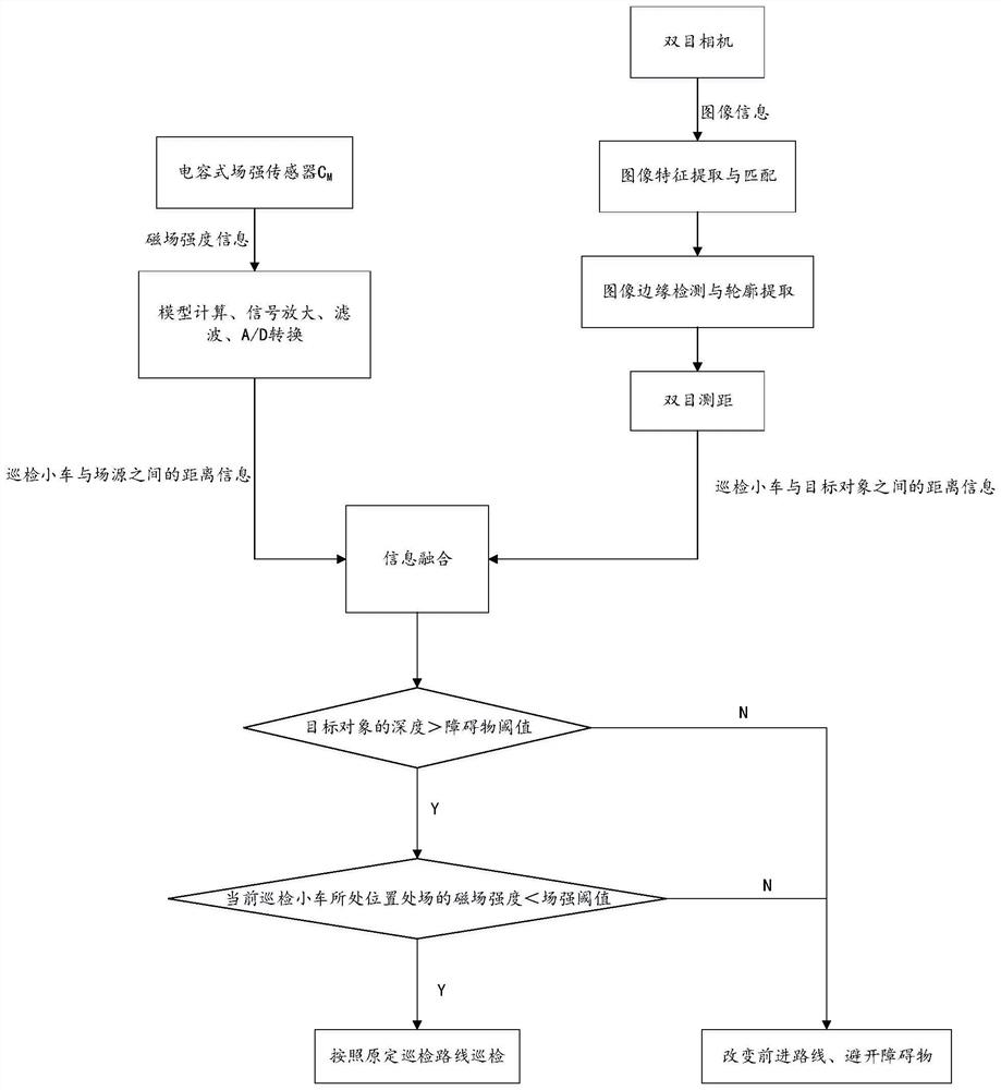
[0044] see figure 1 .

[0045] In this specific embodiment, a substation inspection robot system is provided, and the robot includes:

[0046] It has a carrying platform, an inspection trolley for carrying other components and driving along the ground to inspect the substation environment, a field strength sensor for real-time detection of electric field or magnetic field strength, an image collector for obtaining real-time images, and an inspection vehicle for A control center that analyzes the re...


PUM


Abstract

The invention discloses a transformer substation inspection robot system. A robot comprises an inspection trolley, a field intensity sensor used for detecting an electric field or magnetic field intensity in real time, an image collector used for obtaining a real-time image, and a control center used for analyzing the real-time pose of the inspection trolley and making path planning for the inspection trolley. The field intensity sensor and the image sensor are carried on the inspection trolley and are connected with the inspection trolley; the inspection trolley, the field intensity sensor and the image sensor interact with the control center. Compared with the prior art, the inspection system and the inspection method provided by the invention adopt a means of combining image processing and field intensity detection to adapt to the specific conditions that the number of components in the transformer substation is large, and electric field or magnetic field interference exists around power equipment; a safe, effective and multi-dimensional decision basis is provided for obstacle avoidance of the inspection trolley, and the unmanned automatic inspection process of the inspection trolley is ensured to be smoothly carried out.

Description

technical field [0001] The invention belongs to the technical field of electric power detection, and in particular relates to an automatic inspection robot for electric power equipment facing substations. Background technique [0002] A variety of power equipment is installed in the substation. The power department needs to conduct routine inspections on a regular basis to check the operation of each power equipment to ensure that each equipment is working normally and to discover potential safety hazards in time. [0003] Under the existing power system, the power sector mainly relies on operation and maintenance personnel to complete routine inspections of substations in the form of manual inspections. However, it is worth noting that when the inspection, recording, and maintenance of power equipment in substations are carried out by means of manual inspection, due to the large workload of on-site operations, low efficiency of manual inspection, high requirements for human...

Claims


Application Information

Patent Timeline
Patent Type & Authority Applications(China)
IPC IPC(8): B25J9/16B25J11/00B25J19/02B25J19/04
CPCB25J11/00B25J9/161B25J9/1664B25J9/1661B25J19/027B25J19/04
Inventor 陈星筑左益芳王龙翔
Owner 信通院车联网创新中心(成都)有限公司
Why Eureka
Try Eureka