Eureka AIR delivers breakthrough ideas for toughest innovation challenges, trusted by R&D personnel around the world.

Sound wave sensor and system for detecting temperature field in boiler

A sound wave sensor, internal temperature technology, applied in thermometers, thermometers with physical/chemical changes, instruments, etc., can solve the problems of unstable working conditions, attenuation of sound wave signals, inaccurate temperature, etc., to achieve balance and optimize combustion, prolongation Service life, the effect of reducing the delivery

Pending Publication Date: 2022-03-15
北京国电电力有限公司大连开发区热电厂
View PDF0 Cites 0 Cited by
  • Summary
  • Abstract
  • Description
  • Claims
  • Application Information

AI Technical Summary

Problems solved by technology

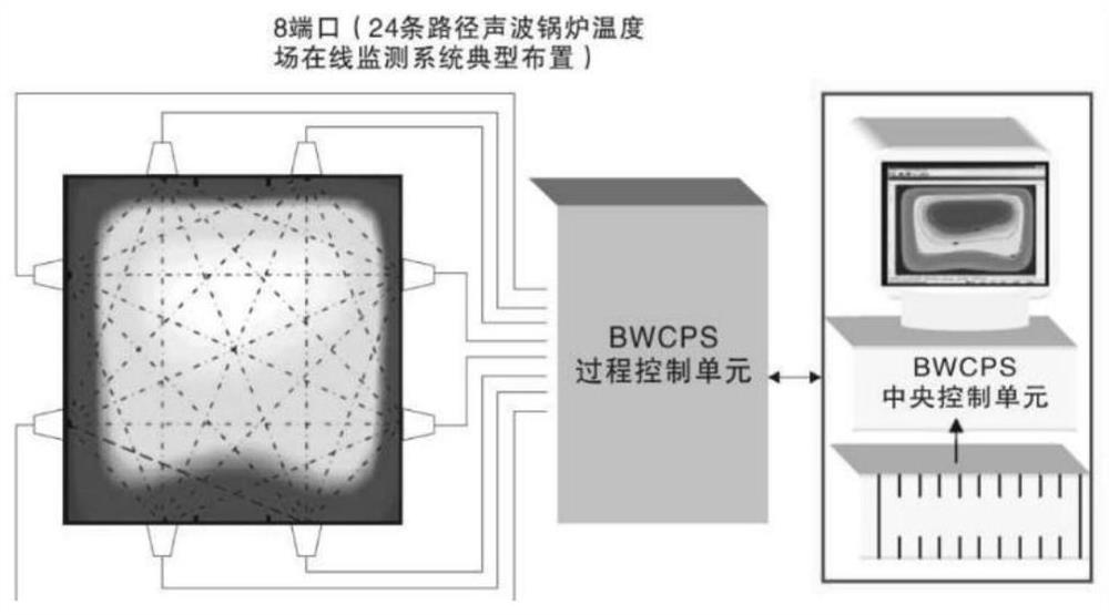
Therefore, the safe and efficient operation of the boiler is directly related to the overall economy and safety. In view of its huge energy consumption and emissions, the boiler has long been an important supervision object of the environmental protection department. Because the combustion process in the boiler furnace is a very complicated Suspension combustion, the working condition is extremely unstable, if the temperature field in the furnace cannot be determined, the operating condition of the boiler cannot be adjusted in time, which will easily lead to insufficient combustion, low thermal efficiency, and more dust and other pollutants , What's more, there are major safety accidents such as explosions, so the monitoring of the furnace temperature field is particularly important. In recent years, for the monitoring of the furnace temperature field, the technology of acoustic temperature measurement has become more and more mature. The attenuation in the furnace with high temperature and high dust is serious, which leads to inaccurate monitoring of the temperature in the boiler by using the acoustic wave sensor

Method used


Image

  • Sound wave sensor and system for detecting temperature field in boiler
  • Sound wave sensor and system for detecting temperature field in boiler
  • Sound wave sensor and system for detecting temperature field in boiler

Examples


Embodiment Construction

[0037] In order to make the purpose, technical solutions and advantages of the embodiments of the present application clearer, the technical solutions in the embodiments of the present application will be clearly and completely described below in conjunction with the drawings in the embodiments of the present application. Obviously, the described embodiments are only It is a part of the embodiments of this application, not all of them. The components of the embodiments of the application generally described and illustrated in the figures herein may be arranged and designed in a variety of different configurations. Accordingly, the following detailed description of the embodiments of the application provided in the accompanying drawings is not intended to limit the scope of the claimed application, but merely represents selected embodiments of the application. Based on the embodiments of the present application, every other embodiment obtained by those skilled in the art withou...


PUM


Abstract

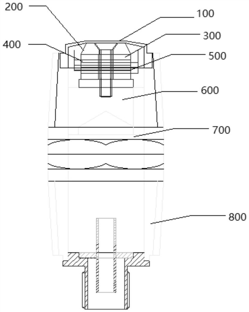
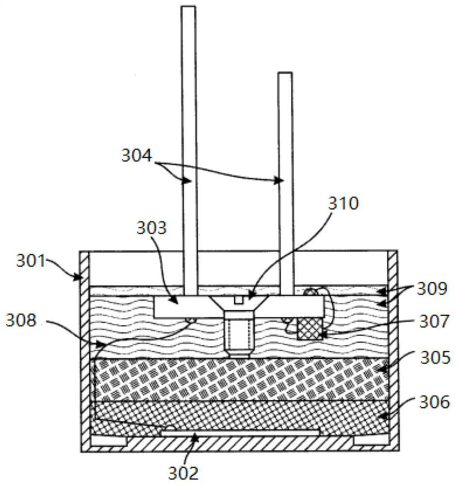
The invention provides a sonic sensor for detecting a temperature field in a boiler. The sonic sensor comprises a shell, an edge clamping bending vibration disc, a longitudinal vibration amplitude-change pole, a piezoelectric ceramic stack, a heavy mass block and a tail end cover, wherein the edge clamping bending vibration disc is inversely welded at one end of the shell and is used for receiving sound wave information fed back by a temperature field in a boiler; the piezoelectric ceramic stack is arranged in the shell, and the piezoelectric ceramic stack is connected with an edge clamping bending vibration disc through a longitudinal vibration amplitude-change pole and used for converting the sound wave information into an electric signal; the piezoelectric ceramic stack is connected with the heavy mass block through a fixing bolt, and the tail end cover is arranged at the end, away from the fixing bolt, of the heavy mass block and used for fixing the heavy mass block. According to the sensor, acoustic signals are amplified through the piezoelectric ceramic pile, the accuracy of acoustic detection can be guaranteed, and the sensor is more suitable for the environment where dust is gathered in a hearth.

Description

technical field [0001] The present application relates to the technical field of boiler monitoring, in particular to an acoustic wave sensor and system for detecting the temperature field in a boiler. Background technique [0002] With the development of society, boilers have played an important role in our daily life, especially in the field of power supply and heating. Therefore, the safe and efficient operation of the boiler is directly related to the overall economy and safety. In view of its huge energy consumption and emissions, the boiler has long been an important supervision object of the environmental protection department. Because the combustion process in the boiler furnace is a very complicated Suspension combustion, the working condition is extremely unstable, if the temperature field in the furnace cannot be determined, the operating condition of the boiler cannot be adjusted in time, which will easily lead to insufficient combustion, low thermal efficiency, a...

Claims


Application Information

Patent Timeline
Patent Type & Authority Applications(China)
IPC IPC(8): G01K11/22
CPCG01K11/22
Inventor 周国强赵树龙王政
Owner 北京国电电力有限公司大连开发区热电厂
Why Eureka
Eureka Blog
Learn More