
Universal strain clamp anti-falling external member and installation method

A general-purpose, tension-resistant technology, applied in the direction of adjusting/maintaining mechanical tension, overhead line/cable equipment, etc., it can solve the problems that the fixture cannot be installed and used, and the protective device cannot be installed smoothly, and achieves the effect of good versatility.

Pending Publication Date: 2022-03-15
STATE GRID FUJIAN ELECTRIC POWER CO LTD +2
View PDF1 Cites 0 Cited by
  • Summary
  • Abstract
  • Description
  • Claims
  • Application Information

AI Technical Summary

Problems solved by technology

And because it relies on the two screws connected in series to the U-shaped pull ring of the steel anchor ring of the steel anchor ring of the wire tension compression to withstand the tension of the wire after penetrating the earring holes on both sides, it will always maintain a moderate tension state, and in case the wire is tension resistant There will be no impact force when the connection is dropped; however, since the U-shaped pull ring needs to be installed through the steel anchor ring of the wire tension-resistant connection pipe, in practical applications, especially some ultra-high voltage line equipment, due to the force requirements Different, so the diameter of the U-shaped pull ring may not be able to pass through the steel anchor ring of the wire tension crimping pipe after the diameter is increased, resulting in the failure of the original protective device to be installed smoothly, and it cannot be installed and used with other fixtures that do not have a steel anchor ring structure

Method used


Image

  • Universal strain clamp anti-falling external member and installation method
  • Universal strain clamp anti-falling external member and installation method
  • Universal strain clamp anti-falling external member and installation method

Examples


Embodiment Construction

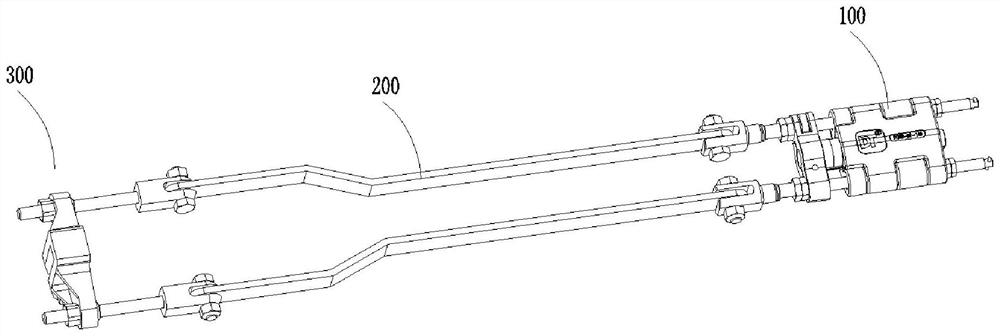
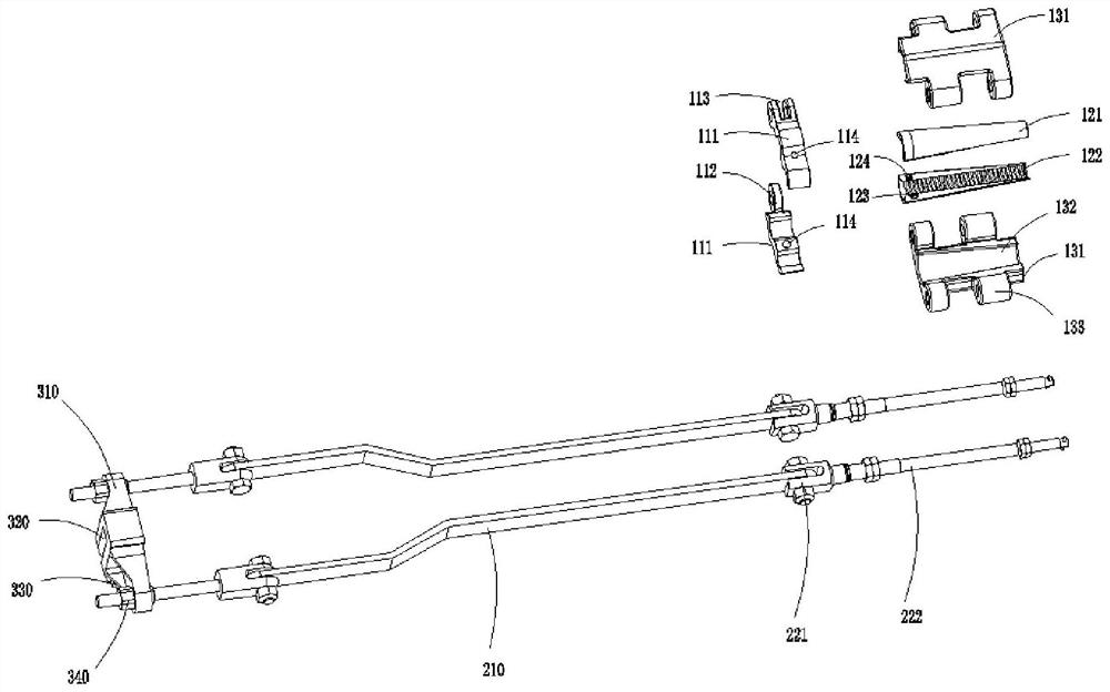
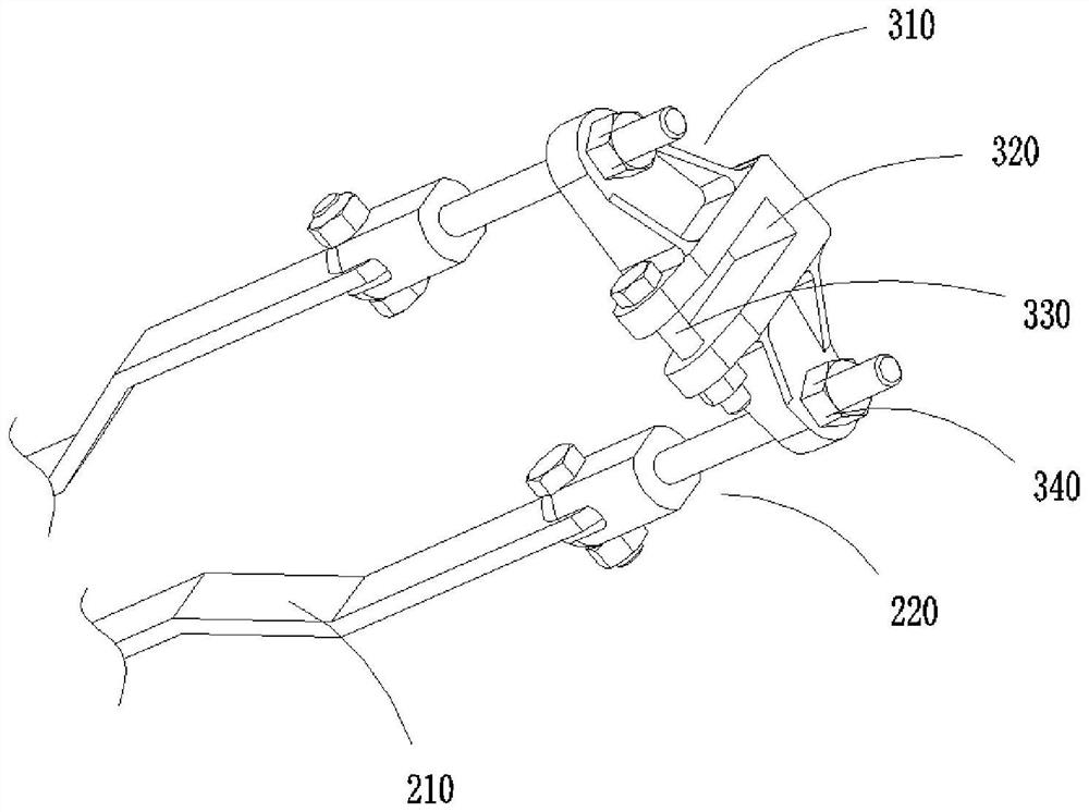
[0028] The technical solutions in the embodiments of the invention will be clearly and completely described below in conjunction with the accompanying drawings in the embodiments of the invention. Obviously, the described embodiments are only part of the embodiments of the invention, not all of them. Based on the embodiments of the invention, all other embodiments obtained by persons of ordinary skill in the art without making creative efforts belong to the protection scope of the invention.

[0029] see figure 1 , the invention provides a technical solution: a general-purpose strain clamp anti-falling kit, including a front self-locking clamp 100, a pull rod 200 and a rear end fastening clamp 300, and the front self-locking clamp 100 is fixed on the front end tension wire , the rear end fastening fixture 300 is fixed on the end of the U-shaped ring, PT adjustment plate or PD extension plate at the rear end, and the tie rod 200 is provided with two groups of left and right sym...


PUM


Abstract

The invention discloses a universal strain clamp anti-falling external member and an installation method, and belongs to the technical field of electric power protection fitting structures. The universal strain clamp anti-falling external member comprises a front-end self-locking clamp, a pull rod piece and a rear-end buckling clamp, the front-end self-locking clamp is fixed on a front-end strain wire, and the pull rod piece is fixed on the rear-end buckling clamp; the front-end self-locking clamp is fixed at the end part of the front-end self-locking clamp, the rear-end buckling clamp is fixed at the end part of the rear-end U-shaped ring, the PT adjusting plate or the PD extension plate, the two groups of pull rod pieces are arranged in bilateral symmetry and are respectively connected with the left and right ends of the front-end self-locking clamp and the rear-end buckling clamp, and the protective hardware fitting for bearing the mechanical tension of the wire is only composed of three parts. The tightening clamp adopts an inner taper sleeve and an outer taper sleeve, is light and simple, is convenient to install, and is installed without depending on a steel anchor ring of a wire tension crimping pipe, so that the anti-falling external member for the strain clamp has better universality.

Description

technical field [0001] The invention relates to the technical field of electric power protection fittings structure, in particular to a general-purpose strain clamp anti-falling kit and an installation method. Background technique [0002] The wire crimping tube in the running line, due to insufficient pressure during hydraulic crimping, the deformation of the mold did not reach the proper compression ratio, or the connection of new and old wires, inadequate purification work, and insufficient tightening force of the bolts on the drainage plate of the tension clamp Problems such as crimping tube pulling out, breakage, heat and burns may cause the wire to fall to the ground, and the power supply of the line will be interrupted. Especially the tension-type crimping tubes of transmission lines spanning high-speed railways, highways, rail transit and important municipal facilities, once broken, it will cause a series of serious secondary hazards. Most of the current protective ...

Claims


Application Information

Patent Timeline
Patent Type & Authority Applications(China)
IPC IPC(8): H02G7/02H02G1/04
CPCH02G7/02H02G1/04
Inventor 冯振波吴晓杰蔡金林郑孝干杨毅豪李宽宏张良发林信恩卓晗林华育徐鹏飞刘行洲林善泉赵新丰
Owner STATE GRID FUJIAN ELECTRIC POWER CO LTD
Learn More