
Electric power protector capable of preventing electric leakage caused by false tripping

A leakage protector and protector technology, applied in the field of power safety, can solve the problems of lack of switch anti-closing limit function, faulty tripping of the leakage protector switch, affecting the safety of operators, etc., so as to improve the safety of use and avoid mistakes. The effect of jumping, which is conducive to heat dissipation

Pending Publication Date: 2022-03-15
徐增杰
View PDF0 Cites 0 Cited by
  • Summary
  • Abstract
  • Description
  • Claims
  • Application Information

AI Technical Summary

Problems solved by technology

[0005] The purpose of the present invention is to provide a power protector for preventing false tripping and leakage, to solve the above-mentioned background technology. The existing leakage protectors on the market are generally directly fixed and installed on the installation surface for use. In the environment, the external vibration is relatively large, and the vibration can be directly transmitted to the leakage protector through the wall and other installation surfaces, which may easily cause the switch of the leakage protector to trip by mistake, affecting its normal use. The anti-closing limit function of the switch, when other personnel push the switch during maintenance work, will directly affect the safety of the operator

Method used


Image

  • Electric power protector capable of preventing electric leakage caused by false tripping
  • Electric power protector capable of preventing electric leakage caused by false tripping
  • Electric power protector capable of preventing electric leakage caused by false tripping

Examples


Embodiment Construction

[0031] The following will clearly and completely describe the technical solutions in the embodiments of the present invention with reference to the accompanying drawings in the embodiments of the present invention. Obviously, the described embodiments are only some, not all, embodiments of the present invention. Based on the embodiments of the present invention, all other embodiments obtained by persons of ordinary skill in the art without making creative efforts belong to the protection scope of the present invention.

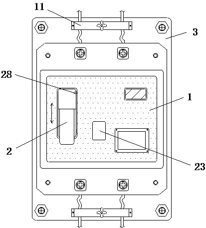
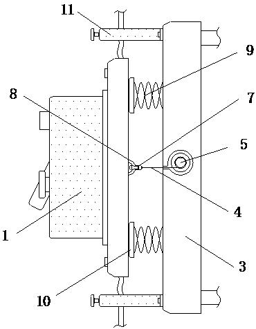
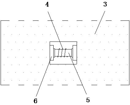
[0032] see Figure 1-8, the present invention provides a technical solution: a power protector for preventing false tripping and leakage, including a leakage protector main body 1 and a switch 2, and the switch 2 is installed on the front side of the leakage protector main body 1 to control the opening of the leakage protector main body 1 and closed, the rear side of the leakage protector main body 1 is provided with a mounting plate 3, and the mounting plate ...


PUM


Abstract

The invention discloses a false tripping and electric leakage prevention electric power protector, which comprises an electric leakage protector main body and a switch, and is characterized in that the switch is installed at the front side of the electric leakage protector main body to control the opening and closing of the electric leakage protector main body, and the rear side of the electric leakage protector main body is provided with an installation plate; the installation plate is fixedly arranged on the installation surface and provides support for the leakage protector body, the rear side of the leakage protector body is connected with a traction rope, the rear end of the traction rope is connected with a winding shaft, a winding shaft bearing is installed in the installation plate, and a torsion spring is arranged at the end of the winding shaft and provides rotation driving force for the winding shaft. The electric power protector capable of preventing mistaken tripping and electric leakage is provided with the traction rope, the buffer spring and the sliding plate, the mounting plate is connected with the electric leakage protector main body through the traction rope, and meanwhile, the electric leakage protector main body is erected in cooperation with the buffer spring and the sliding plate, so that vibration force borne by the mounting plate subsequently is prevented from being directly transmitted to the electric leakage protector main body.

Description

technical field [0001] The invention relates to the technical field of electric power safety, in particular to an electric power protector for preventing false tripping and electric leakage. Background technique [0002] Leakage protector is a common circuit protection switch. It can automatically disconnect the switch when detecting current leakage to form an automatic circuit breaker. It is widely used in daily life, but there are still some shortcomings in the use of existing leakage protectors. at: [0003] Existing leakage protectors are generally fixed and installed directly on the installation surface for use. In the construction site environment or decoration environment, the external vibration is relatively large, and the vibration can be directly transmitted to the leakage protector through the installation surface such as the wall, which may easily lead to leakage The switch of the protector has false tripping, which affects its normal use, and the existing leaka...

Claims


Application Information

Patent Timeline
IPC IPC(8): H02H3/32H02H3/02H02G3/02F16F15/067
CPCH02H3/32H02H3/02H02G3/02F16F15/067
Inventor 徐增杰
Owner 徐增杰
Learn More