
Medicine applying treatment equipment for department of stomatology

A processing equipment and stomatological technology, applied in the direction of pharmaceutical equipment and other medical equipment, can solve the problems of large space occupation, small operating space, low efficiency, etc., and achieve the effect of increasing cost and increasing the effect of use

Pending Publication Date: 2022-03-18
曾贤伟
View PDF0 Cites 0 Cited by
  • Summary
  • Abstract
  • Description
  • Claims
  • Application Information

AI Technical Summary

Problems solved by technology

[0004] In order to overcome the disadvantages of using tweezers to clamp the disinfectant cotton, the efficiency is low and the uniform application of the drug cannot be guaranteed. Most of the existing dilators occupy a large space, the operating space is small, it is not convenient to apply the drug or inspection, and the shortcomings of the complicated operation need to be solved. The technical problem is: to provide a simple operation, rely on the machine to open the mouth, and use a dispersed nozzle to apply medicine to the oral cavity to ensure the quality of the medicine used in stomatology.

Method used


Image

  • Medicine applying treatment equipment for department of stomatology
  • Medicine applying treatment equipment for department of stomatology
  • Medicine applying treatment equipment for department of stomatology

Examples


Embodiment 1

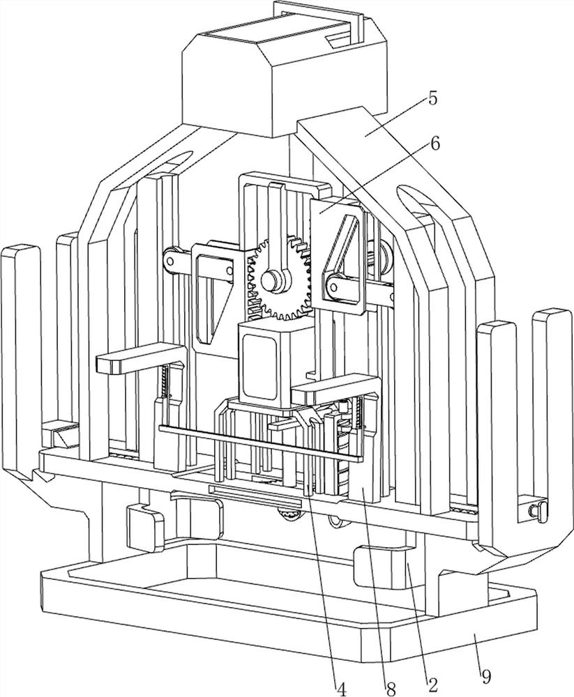
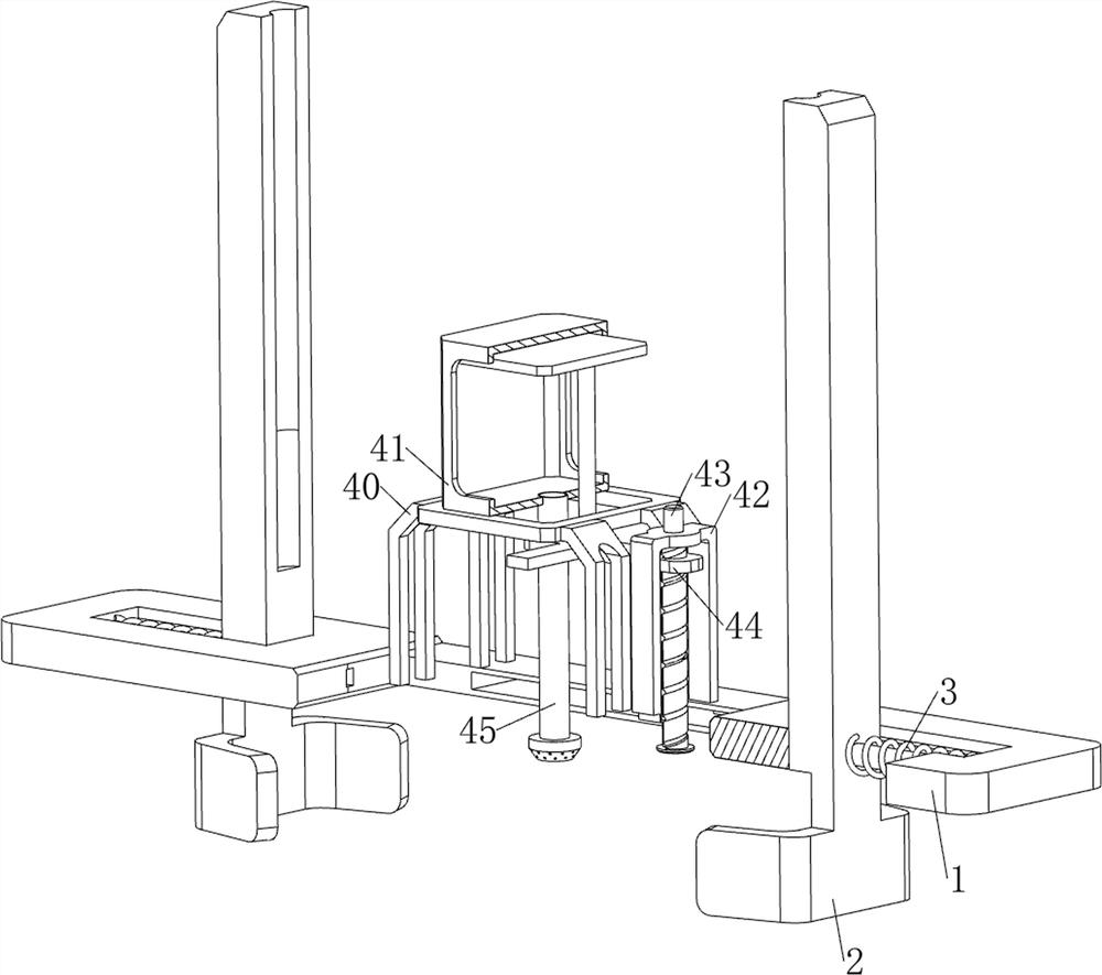
[0028] A kind of treatment equipment for stomatology, such as Figure 1 to Figure 4 Shown, comprise limiting plate 1, movable plate 2, the first spring 3, dispensing mechanism 4 and infusion mechanism 5, all left and right sides of limiting plate 1 inner wall are slidingly provided with movable plate 2, and movable plate 2 outsides are all connected with limiter. A first spring 3 is connected between the position plate 1, a medicine dispensing mechanism 4 is arranged on the middle side of the top of the limit plate 1, and an infusion mechanism 5 is connected between the left and right sides of the top of the limit plate 1.

[0029] The drug dispensing mechanism 4 includes a first support frame 40, a first charging frame 41, a second support frame 42, a screw mandrel 43, an extruding plate 44 and an infusion tube 45, and the middle side of the top of the limiting plate 1 is provided with a first support frame 40, the top of the first support frame 40 is provided with a first ch...

Embodiment 2

[0033] On the basis of Example 1, such as figure 1 , Figure 5 and Figure 6 As shown, a spreading mechanism 6 is also included, and the spreading mechanism 6 includes a limit frame 60, a first gear 61, a rotating rod 62, a tooth block 63, a second movable block 64, a third spring 65 and a support plate 66, and the first A limit frame 60 is connected between the left and right sides of a charging frame 41, and the middle part of the limit frame 60 is connected with a rotating rod 62 in a rotating manner. The tooth block 63 is provided, the left and right sides of the top of the limit plate 1 are provided with a support plate 66, and the top of the support plate 66 is slidingly provided with a second movable block 64, and the second movable block 64 is connected to the inner side of the support plate 66. There is a third spring 65 .

[0034] Also comprise transmission mechanism 7, and transmission mechanism 7 comprises tooth bar 70, back-moving spring 71, transmission assemb...

Embodiment 3

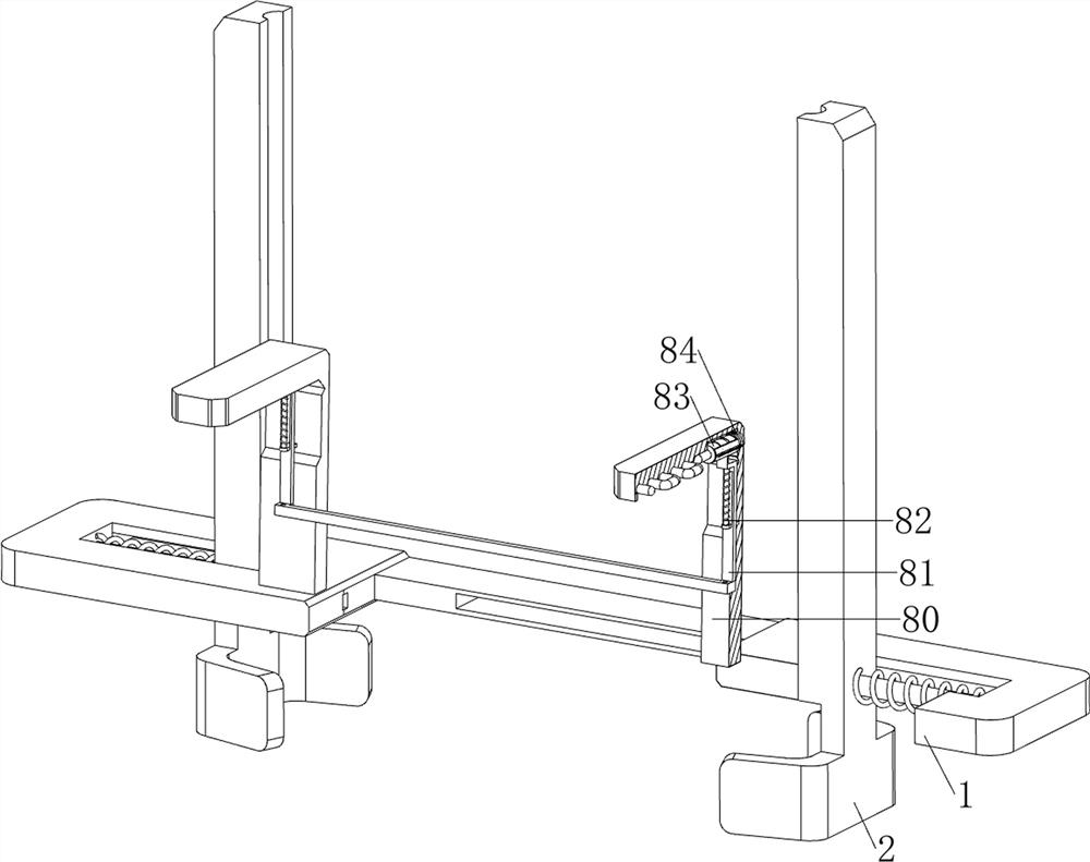
[0037] On the basis of Example 2, such as figure 1 , Figure 7 and Figure 8 As shown, it also includes a lighting mechanism 8, the lighting mechanism 8 includes a support rod 80, a movable rod 81, a fourth spring 82, a battery 83 and a fifth spring 84, and the left and right sides of the top of the limiting plate 1 are provided with a support rod 80. , the top of the inner wall of the support rod 80 is provided with a light bulb, and the sliding type between the front sides of the support rod 80 is provided with a movable rod 81, and a fourth spring 82 is connected between the movable rod 81 and the support rod 80. a battery 83, and a fifth spring 84 is connected to the top rear side of the inner wall of the support rod 80.

[0038] Also includes a protection mechanism 9, the protection mechanism 9 includes a fixed frame 90, a buckle 91 and a sixth spring 92, the bottom of the limit plate 1 is symmetrically connected with the fixed frame 90, and the outside of the fixed fra...


PUM


Abstract

The invention relates to medicine applying treatment equipment, in particular to medicine applying treatment equipment for the department of stomatology. The medicine applying treatment equipment for the department of stomatology is easy to operate, the mouth is opened through a machine, meanwhile, medicine is applied to the oral cavity through dispersive spray heads, and the medicine applying quality is guaranteed. Medicine applying treatment equipment for the department of stomatology comprises a limiting plate, movable plates, first springs, a medicine discharging mechanism and an infusion mechanism, the movable plates are arranged on the two sides of the inner wall of the limiting plate in a sliding mode, the first springs are connected between the outer sides of the movable plates and the limiting plate, the medicine discharging mechanism is arranged on the middle side of the top of the limiting plate, and the infusion mechanism is connected between the two sides of the top of the limiting plate. The movable plate is driven to move outwards to open the mouth of the patient, medicine applying can be matched, and the situation that the patient is stimulated by medicine, the mouth is closed, medicine applying is affected, and meanwhile cost is increased is prevented.

Description

technical field [0001] The invention relates to a medicine feeding processing device, in particular to a medicine feeding processing device used in the department of stomatology. Background technique [0002] Stomatology, one of the classifications of medical disciplines. At present, when medical staff need to clean the mouth of patients who are clinically limited due to their own disease, inconvenient to move after surgery, or receive oral treatment, they need to first open the patient's mouth to facilitate oral hygiene. Then use tweezers to clamp the anti-bacterial cotton to apply the drug, which is inefficient and cannot ensure uniform drug application. The existing dilator occupies a large space and the operation space is small, which is not convenient for drug application or inspection, and the operation is complicated. [0003] Therefore need to design a kind of simple operation, rely on the machine to stretch the mouth, use the dispersive nozzle to carry out medicine ...

Claims


Application Information

Patent Timeline
Patent Type & Authority Applications(China)
IPC IPC(8): A61M31/00
CPCA61M31/00A61M2205/587A61M2210/0625A61M2210/005
Inventor 曾贤伟
Owner 曾贤伟
Learn More